Common Vision Blox 15.0
All Classes Namespaces Files Functions Variables Typedefs Enumerations Enumerator Properties Events Friends Modules Pages
Intrinsic and Extrinsic Calibration using the AQS12 Target

If you have decided based on your setup and requirements, that it is best to perform the calibration using the AQS12 target, you fill find a detailed guide in the following sections.

With the AQS12 calibration the following calibration corrections can be estimated:

Calibration Correction Link to Calibration Theory
Homography Transformation of Range Map Coordinates to Metric Coordinates
Encoder step (scale in Y)
Correction of inclined laser plane Correction of an Inclined Laser Plane and Extrinsic Calibration
Rotation and translation to given coordinate system (rigid-body transformation)

AQS12 Calibration Target

In order to estimate the calibration corrections, a target with precisely defined reference points is required. CVB currently supports a diamond-shaped calibration pattern, called AQS12 for this purpose. The AQS12 has a distinct shape with 8 planes and 12 feature points resulting from the intersection points of these planes. While the overall size of the target can vary, the proportions of the example AQS12 shown in this section should be largely maintained, as they are important for the internal algorithm. Additionally, the correct order of the points on the pattern must be observed, depending on the camera setup.

AQS12 - Calibration Target

AQS12 Calibration Target Design

The dimensions of the calibration target should be similar to the example shown in the figures below. In any case it should meet the following requirements:

  • The base plane has to contain enough area: The number of pixels on the base plane has to be (significantly) larger than the number of pixels on the roof.
  • Points 1-6 and 7-12 respectively have to lie on the same plane. Base plane and roof have to be parallel. The shape of the object may not be changed, i.e. parallel lines must remain parallel, and the object has to be symmetric.
  • Calibration points 1, 8 and 12 projected to the base plane should lie on a line, same for 4, 9 and 11.
  • In order to get accurate calibration results, the surfaces should be non-specular.
  • The target has to be manufactured from stable (also temperature-stable) material.
  • Check, if the slopes of the calibration target can be acquired under the triangulation angle needed for your application.
  • Be aware that measurements taken far from the target area may have higher errors, as residual errors propagate with an increasing distance to the calibration target. To minimize these errors, it is essential to ensure that the AQS12 target adequately covers the area where measurements will be performed in the future.
  • Due to the symmetry of the AQS12 target, it is highly recommended to attach a small marker to one of the edges on the base plane. This marker helps distinguish between the top and bottom as well as the left and right sides of the target in the range map. The marker can be applied after the target has been manufactured.

The following figures show an example AQS12 with optimal dimensions. It is best to scale it to the dimensions of your current setup.
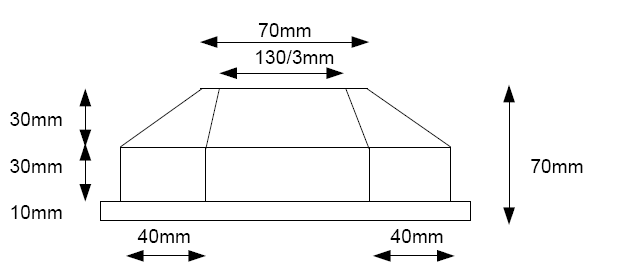
AQS12 Top View
AQS12 Top View
AQS12 Side View


AQS12 Side View

The world coordinates of the reference points for the example shown in the figure above are listed in the following table:

Point X [mm] Y [mm] Z [mm]
    movement direction away from camera movement direction towards camera  
1 0 35 -35 60
2 10 21.667 -21.667 60
3 10 -21.667 21.667 60
4 0 -35 35 60
5 -10 -21.667 21.667 60
6 -10 21.667 -21.667 60
7 0 75 -75 30
8 30 35 -35 30
9 30 -35 35 30
10 0 -75 75 30
11 -30 -35 35 30
12 -30 35 -35 30
Height 60      

The first column represents the x-coordinate, the second the y-coordinate, and the third the z-coordinate. The single value in the last line specifies the height difference between the roof and the base plane. Pay close attention to the order of the points: If the movement direction is towards the camera, the point order will change, as explained in the next section.

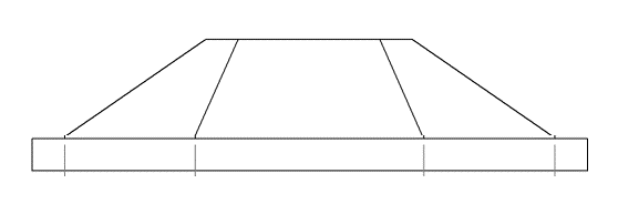
It is worth noting that the vertical walls of the calibration target are not mandatory. The target can also consist of just the base and top planes with six faces (see the figure below):

AQS12 Target without Walls

Setup Requirements

Additionally to the appropriate design of the target, the following specifications should be considered during the acquisition:

  • The calibration target has to be moved at constant speed or synchronized with the camera by an encoder, so that the distances between successive profiles are always equal.
  • The image used for the calibration should contain only points belonging to the calibration target. In case the acquired range map shows more than the pattern, use according CVB functions where an area of interest can be specified.
  • The axis on which the points 7, 1, 4 and 10 are located, should be (more or less) parallel to the motion direction. The target may be rotated clockwise about 90° (point 7 right, point 10 left). In this case points 7, 1, 4 and 10 have to be more or less parallel to the x axis.
  • The z-axis of the calibration target should be perpendicular to the motion plane.
  • The range map acquired from the AQS12 shape should definitely include the base plane (i. e. the points on the base plane should be neither 0 nor whatever value the actually used 3D sensor defines for invalid points).

Note, that the order of the reference points in the range map depends on the direction of movement and the camera's mounting. If the movement direction is away from the camera, the point order in the range map corresponds directly to the real-world arrangement. In this case the 7th point will appear at the top, and the 10th point at the bottom:

AQS12 setup
AQS12 setup range map

If the movement direction is towards the camera, the points are mirrored along the y-axis (or along the rows). In this case, the 10th point will appear in the range map at the top, and the 7th point at the bottom:

AQS12 setup
AQS12 setup range map

Attention
When using the AQS12Piece class (e.g., Cvb::Foundation::Metric::AQS12::AQS12Piece, Stemmer.Cvb.Foundation.AQS12Piece or cvb.foundation.AQS12Piece), it is essential to understand that the point order is determined by the range map's coordinate system. In the range map, the topmost point corresponds to point #7, and the bottommost point corresponds to point #10.

If the point order appears mirrored in the range map due to the camera's orientation or mounting, you must adjust the corresponding real-world points passed to the AQS12Piece object to match this mirrored order. The following table illustrates how the point numbers in the range map relate to their counterparts in the real-world coordinate system, assuming that the movement direction is towards the camera:

roof base
Point number as used in the AQS12Piece class. 1 2 3 4 5 6 7 8 9 10 11 12
Corresponding point number on the real-world AQS12 target. 4' 3' 2' 1' 6' 5' 10' 9' 8' 7' 12' 11'

By defining the points as shown above, the calibrated and transformed points will be in a right-handed trihedron. A code example demonstrating how to define the reference points using the AQS12Piece class is available here.

Recommendation for rectified point clouds:

For subsequent image processing on a rectified point cloud, it is often advisable to transform the point cloud into a left-handed trihedron, as image coordinates typically follow a left-handed system.

When rectifying a point cloud, the x-coordinates correspond to the image columns, and the y-coordinates correspond to the image rows. While the X-axis of the point cloud and the column axis of the image both point to the right, the Y-axis of a right-handed trihedron points upward, whereas the row axis of the image points downward. Conversely, the Y-axis of a left-handed trihedron also points downward, aligning with the image coordinate system. As a result, rectifying a point cloud from a right-handed trihedron will cause it to appear mirrored in the image.

To transform the point cloud into a left-handed trihedron, mirror the input reference points by multiplying their y-coordinates by -1.

It is essential to distinguish between two operations:

  • Mirroring the point order or swapping points (as required when the movement direction is towards the camera).
  • Mirroring points along the y-axis (as required for rectifying the point cloud).

When working with idealized coordinates, such as those derived from a CAD model (like for the example AQS12 depicted above), these operations may yield identical results. However, with precisely measured reference coordinates, the two approaches can produce different outcomes. The table below demonstrates this distinction with exemplary coordinates for points #1 and #4:

Original Coordinates Point Order Mirrored/Points Swapped Y Coordinates Mirrored
#1 (0,30,60.1) (0,-30,59.9) (0,-30,60.1)
#4 (0,-30,59.9) (0,30,60.1) (0,30,59.9)

AQS12 Calibration with CVB

The following sections will provide a detailed guide on how to perform the AQS12 calibration using the CVB SDK. Using the AQS12 you can perform three types of calibration:

  • Use case 1: Extrinsic calibration to correct for an inclined laser plane.
  • Use case 2: A straightforward rigid-body transformation.
  • Use case 3: Combined extrinsic calibration and homography estimation.
Calibration Correction Extrinsic Calibration Intrinsic and Extrinsic Calibration
Use Case 1 Use Case 2 Use Case 3
Homography
Encoder step (scale in Y)
Correction of inclined laser plane
Rotation and translation to given coordinate system (rigid-body transformation)

Example Programs

Example programs for each use case are available in C++, .NET and Python. These can be found in your CVB setup under the following directories:

  • C++: %cvb%Tutorial/Foundation/Cvb++/
  • .NET: %cvb%Tutorial/Foundation/Cvb.Net/
  • Python: %cvb%Tutorial/Foundation/CvbPy/

Alternatively, the examples can be accessed via the following links:

Extrinsic Calibration Intrinsic and Extrinsic Calibration
Use Case 1 Use Case 2 Use Case 3
C++ CppMetricCalibrationInclinationLaserPlane CppMetricCalibrationRigidBodyTrafo CppMetricCalibration
.NET Metric3DCalibrationLaserPlane Metric3DCalibrationRigidBodyTransform Metric3DCalibration
Python MetricCalibrationInclinationLaserPlane MetricCalibrationRigidBodyTransformation MetricCalibration

Prerequisites

The estimation of an intrinsic and/or extrinsic calibration using the AQS12 target is implemented in the CVMetric.dll. To execute the code snippets provided in this documentation, following DLLs are additionally required:

To utilize this functionality, the following namespaces and include files are required:

#include "cvb/point_cloud_factory.hpp"
#include "cvb/calibrator_3d.hpp"
#include "cvb/foundation/metric_aqs12.hpp"
using namespace Cvb::Foundation::Metric;

import cvb

Defining and Fixing AQS12 Reference Points

Once a stable AQS12 target with precisely measured coordinates is manufactured and a range map of the target is acquired, the calibration process can begin. The first step involves defining the reference points using the AQS12Piece class. For critical details about the camera setup and the correct point order, refer to this section.

In addition to specifying the reference points, you can provide the target's height, i.e. the height difference between roof and base plane. However, this value is optional if the reference z-coordinate of the base plane is set to zero. In such cases, you can leave the height parameter as zero, allowing the algorithm to calculate the target’s height automatically.

// reference points
std::array< Cvb::Point3D<double>, 12> points =
{ {
{0,35,60},
...
{-30,35,30},
} };
// Create AQS12 object.

// reference points
var points = new Point3Dd[]
{
new Point3Dd(0,35,60),
...
new Point3Dd(-30,35,30)
};
// Create AQS12 object.
var aqs12 = new AQS12Piece(points, 60);

# reference points
points = [
cvb.Point3D(0,35,60),
...
cvb.Point3D(-30,35,30)]
# Create AQS12 object
aqs12 = cvb.foundation.AQS12Piece(points, 60)

The AQS12Piece object is required as an initial step for creating a calibration configuration object. For more details, refer to the documentation of Cvb::Foundation::Metric::CalibrationConfiguration, Stemmer.Cvb.Foundation.CalibrationConfiguration and cvb.foundation.CalibrationConfiguration or to the following sections.

Use Case 1 and 2: Extrinsic Calibration

If you only need to perform an extrinsic calibration, you will require a calibrated point cloud. This means your sensor must either provide a point cloud directly or a range map paired with a calibration file. If you have already performed an intrinsic calibration of your setup using the ZigZag target, you can proceed with extrinsic calibration as a subsequent step, too.

To get started, follow these initial steps:

  • Create intrinsically calibrated organized dense point cloud.
  • Create segmentor object for organized dense point clouds.

// create intrinsically calibrated dense point cloud
Cvb::ImagePtr rangemap = Cvb::Image::Load(CVB_LIT("RangemapAQS12.tif"));
auto calibrator = Cvb::Calibrator3D::Load<Cvb::LaserPlaneCalibrator3D>(CVB_LIT("IntrinsicCalibration.json"));
auto cloud = Cvb::PointCloudFactory::Create<Cvb::DensePointCloud>(rangemap->Plane(0), *calibrator, Cvb::PointCloudFlags::Float | Cvb::PointCloudFlags::XYZConfidence);
// create AQS12 segmentor for dense point clouds
auto segmentor = Cvb::Foundation::Metric::AQS12DensePointCloudSegmentor::Create(Cvb::Foundation::Metric::SegmentationMethod::KmeansClustering);
static std::shared_ptr< T > Load(const String &fileName)
static std::shared_ptr< AQS12DensePointCloudSegmentor > Create(const SegmentationMethod method)
static std::unique_ptr< Image > Load(const String &fileName)
static PointCloudPtr Create(const ImagePlane &rangeMap, const Calibrator3D &calibrator, PointCloudFlags flags)
std::shared_ptr< Image > ImagePtr

// create intrinsically calibrated dense point cloud
var rangeMap = Image.FromFile("RangemapAQS12.tif");
var calibrator = Calibrator3D.FromFile<LaserPlaneCalibrator3D>("IntrinsicCalibration.json");
var cloud = calibrator.CreatePointCloud(rangeMap, PointCloudFlags.Float);
// Create AQS12 segmentor for range maps.
var segmentor = new AQS12DensePointCloudSegmentor(SegmentationMethod.KmeansClustering);
PointCloud CreatePointCloud(Image rangeMap)
static Calibrator3D FromFile(string fileName)
__int3264 Image

# create intrinsically calibrated dense point cloud
rangemap = cvb.Image("RangemapAQS12.tif")
calibrator = cvb.Calibrator3D.load("IntrinsicCalibration.json")
cloud = cvb.PointCloudFactory.create_dense(range_map.planes[0], calibrator, cvb.PointCloudFlags.Float)
# create AQS12 segmentor for dense point clouds
segmentor = cvb.foundation.AQS12DensePointCloudSegmentor.create(cvb.foundation.SegmentationMethod.KmeansClustering)
Union[cvb.Calibrator3DAT, cvb.LaserPlaneHomographyCalibrator3D, cvb.LaserPlaneZigZagCalibrator3D, cvb.FactorsCalibrator3D, cvb.MatrixCalibrator3D, cvb.PinholeCameraCalibrator3D] load(str file_name)
cvb.DensePointCloud create_dense(cvb.ImagePlane range_map, cvb.Calibrator3D calibrator, int flags)
cvb.foundation.AQS12DensePointCloudSegmentor create(int method)

Use Case 1: Correcting an Inclined Laser Plane

The section Correction of an Inclined Laser Plane and Extrinsic Calibration explains how an inclined laser plane affects the shear and scale of x, y, and z coordinates. Overall, the transformation of intrinsically calibrated point clouds to world coordinates involves shear, scale, rotation, and translation, as illustrated below:

extrinsic calibration

The shear, scale, and rotation matrices can be combined into a general affine transformation matrix.

In CVB, there are two approaches to estimate the transformation:

  • Affine Matrix: Directly estimate the nine individual elements of the affine matrix (m11, ..., m33) by setting the extrinsic model to AffineMatrix. This method solves a linear system of equations, making it computationally straightforward.
  • Specific Transformation Parameters (recommended!): Estimate parameters for rotation, scale, and shear by setting the extrinsic model to SpecificTransformationParameters. While this approach solves a non-linear system of equations—which might occasionally fail to converge to a reasonable result—it provides more accurate error estimates and thus is generally recommended.

By default, CVB uses the SpecificTransformationParameters model for extrinsic calibration, with encoder step estimation enabled.

To perform the calibration, create an extrinsic calibration configuration object using the previously created AQS12Piece first:

// Create calibration configuration object.
// Change extrinsic model if required.
// config->SetExtrinsicCalibrationModel(Cvb::Foundation::Metric::CalibrationConfiguration::ExtrinsicCalibrationModel::AffineMatrix);
static std::unique_ptr< CalibrationConfiguration > CreateExtrinsic(const AQS12Piece &aqs12)

// Create calibration configuration object.
// Change extrinsic model if required.
// config.Model = CalibrationConfiguration.ExtrinsicCalibrationModel.AffineMatrix;
static CalibrationConfiguration FromAQS12PieceExtrinsic(AQS12Piece piece)

# Create calibration configuration object.
# Change extrinsic model if required
# config.extrinsic_calibration_model = cvb.foundation.ExtrinsicCalibrationModel.AffineMatrix
cvb.foundation.CalibrationConfiguration create_extrinsic(cvb.foundation.AQS12Piece aqs12)

With the previously created calibration configuration object, the segementor object and the point cloud, you can perform the estimation of the calibration parameters:

// Estimate calibration parameters.
auto [transformation, residuals, transformationParameters] = Cvb::Foundation::Metric::CalculateCorrectionOfLaserPlaneInclinationFromAqs12Piece(*cloud, *segmentor, *config);
// Store calibration results to calibrator.
calibrator->SetCorrectionOfLaserPlaneInclination(transformation, transformationParameters);
// Store calibration results in a json file.
calibrator->Save(CVB_LIT("Calibration.json"));
TransformationResult CalculateCorrectionOfLaserPlaneInclinationFromAqs12Piece(const DensePointCloud &cloud, const AQS12DensePointCloudSegmentor &segmentor, const CalibrationConfiguration &config)

// Estimate calibration parameters.
Point3Dd[] residuals;
var affineMatrix = Metric.CalculateCorrectionOfLaserPlaneInclinationFromAqs12Piece(cloud as DensePointCloud, segmentor, config, out residuals);
// Store calibration results to calibrator.
calibrator.CorrectionOfLaserPlaneInclination = Tuple.Create<AffineMatrix3D?, AffineTransformationParameters?>(affineMatrix.Item1, affineMatrix.Item2);
// Store calibration results in a json file.
calibrator.Save("Calibration.json");
static Tuple< AffineMatrix3D, AffineTransformationParameters?> CalculateCorrectionOfLaserPlaneInclinationFromAqs12Piece(DensePointCloud cloud, AQS12DensePointCloudSegmentor segmentor, CalibrationConfiguration config, out Point3Dd[] residuals)

# Estimate calibration parameters.
transformation_, residuals_, transformation_parameters_ = \
# Store calibration results to calibrator.
calibrator.correction_of_laser_plane_inclination = transformation_, transformation_parameters_
# Store calibration results in a json file.
calibrator.save("Calibration.json")
Tuple[cvb.AffineMatrix3D, Optional[List[cvb.Point3D]], Optional[cvb.AffineTransformationParameters]] calculate_correction_of_laser_plane_inclination_from_aqs12_piece(cvb.DensePointCloud cloud, cvb.foundation.AQS12DensePointCloudSegmentor segmentor, cvb.foundation.CalibrationConfiguration config, Optional[cvb.Rect] aoi=None)

The calibration function provides the following results:

  • Affine Matrix and the Translation Vector: These define the transformation from the intrinsically calibrated point cloud to the world coordinate system given by the reference coordinates of the AQS12 target.
  • Individual Calibration Parameters (optional): If SpecificTransformationParameters is selected as extrinsic calibration model, the calibration also provides parameters for shear, scale, and rotation.
  • Residuals: These provide an indication of the calibration accuracy.

Once the calibration results are obtained, it is essential to verify their plausibility and accuracy. For detailed guidance, refer to the section Validation of Calibration.

Use Case 2: Rigid-Body Transformation

If you already have a calibrated point cloud with metric x, y and z coordinates free of errors caused by an inclined laser plane, but wish to transform it into a global coordinate system (e.g., when using multiple sensors), a rigid-body transformation can be applied.

Using the AQS12Piece object, and the segementor object created earlier, you can estimate the rigid-body transformation as follows:

// Estimate rigid-body transformation.
auto [transformation, residuals, transformationParameters] = Cvb::Foundation::Metric::CalculateRigidBodyTransformationFromAqs12Piece(*cloud, *segmentor, aqs12);
// Store extrinsic calibration results to calibrator, if cloud was created from a range map and a calibrator.
// calibrator->SetExtrinsicMatrix(transformation);
RigidBodyTransformationResult CalculateRigidBodyTransformationFromAqs12Piece(const DensePointCloud &cloud, const AQS12DensePointCloudSegmentor &segmentor, const AQS12Piece &aqs12)

// Estimate of rigid-body transformation.
Point3Dd[] residuals;
var trafo = Metric.CalculateRigidBodyTransformationFromAqs12Piece(cloud as DensePointCloud, segmentor, piece, out residuals);
// Store extrinsic calibration results to calibrator, if cloud was created from a range map and a calibrator.
// calibrator.ExtrinsicMatrix = trafo.Item1;
static Tuple< AffineMatrix3D, AffineTransformationParameters > CalculateRigidBodyTransformationFromAqs12Piece(DensePointCloud cloud, AQS12DensePointCloudSegmentor segmentor, AQS12Piece piece, out Point3Dd[] residuals)

# Estimate of rigid-body transformation.
transformation_, residuals_, transformation_parameters_ = \
# Store extrinsic calibration results to calibrator, if cloud was created from a range map and a calibrator
# calibrator.extrinsic_matrix = transformation_
Tuple[cvb.AffineMatrix3D, Optional[List[cvb.Point3D]], cvb.AffineTransformationParameters] calculate_rigid_body_transformation_from_aqs12_piece(cvb.DensePointCloud cloud, cvb.foundation.AQS12DensePointCloudSegmentor segmentor, cvb.foundation.AQS12Piece aqs12, Optional[cvb.Rect] aoi=None)

The function for estimating the rigid-body transformation produces the following results:

  • Affine Matrix and the Translation Vector: These define the transformation from the point cloud into the given world coordinate system given by the reference coordinates of the AQS12 target.
  • Individual Calibration Parameters: Includes rotation angles (with scaling factors fixed at one and shear and inclination set to zero).
  • Residuals: These provide an indication of the calibration accuracy.

Once the calibration results are obtained, it is essential to verify their plausibility and accuracy. For detailed guidance, refer to the section Validation of Calibration.

Use Case 3: Intrinsic and Extrinsic Calibration

If you require both extrinsic and intrinsic calibration, the homography can additionally be estimated using the AQS12 target. However, this method is relatively imprecise and is only suitable for low-accuracy applications. For high-precision measurements, where accurate intrinsic calibration is needed to correct lens distortion and laser line deformation, the ZigZag calibration provided by Stemmer Imaging is recommended.

Begin by loading a range map containing the AQS12 target, then create a segmentor for range maps and a calibration configuration object:

// Load range map.
Cvb::ImagePtr rangemap = Cvb::Image::Load(CVB_LIT("Rangemap.tif"));
// Create calibration configuration object.
// Create AQS12 segmentor for range maps.
auto segmentor = Cvb::Foundation::Metric::AQS12RangeMapSegmentor::Create(Cvb::Foundation::Metric::SegmentationMethod::KmeansClustering);
static std::shared_ptr< AQS12RangeMapSegmentor > Create(const SegmentationMethod method)
static std::unique_ptr< CalibrationConfiguration > Create(const AQS12Piece &aqs12)

// Load range map.
var rangeMap = Image.FromFile("Rangemap.tif");
// Create calibration configuration object.
// Create AQS12 segmentor for range maps.
var segmentor = new AQS12RangeMapSegmentor(SegmentationMethod.KmeansClustering);
static CalibrationConfiguration FromAQS12Piece(AQS12Piece piece)

# Load range map.
rangemap = cvb.Image("Rangemap.tif")
# Create calibration configuration object.
# Create AQS12 segmentor for range maps.
segmentor = cvb.foundation.AQS12RangeMapSegmentor.create(cvb.foundation.SegmentationMethod.KmeansClustering)
cvb.foundation.AQS12RangeMapSegmentor create(int method)
cvb.foundation.CalibrationConfiguration create(cvb.foundation.AQS12Piece aqs12)

By default, the calculation of the homography and the estimation of the encoder step is enabled, with SpecificTransformationParameters set as extrinsic calibration model. For more details about the extrinsic calibration model, refer to Use Case 1: Correcting an Inclined Laser Plane.

Next, proceed with the calibration estimation:

// Estimate calibration parameters.
auto [calibrator, residuals] = Cvb::Foundation::Metric::CreateCalibratorFromAqs12Piece(rangemap->Plane(0), *segmentor, *config);
// Get extrinsic calibration results from calibrator.
auto [transformation, transformationParameters] = calibrator->CorrectionOfLaserPlaneInclination();
// Store calibration results in a json file.
calibrator->Save(CVB_LIT("Calibration.json"));
AQS12CalibratorResult CreateCalibratorFromAqs12Piece(const ImagePlane &imagePlane, const AQS12RangeMapSegmentor &segmentor, const CalibrationConfiguration &config)

// Estimate calibration parameters.
Point3Dd[] residuals;
var calibrator = Metric.CalibratorFromAqs12Piece(rangeMap.Planes[0], segmentor, config, out residuals);
// Get extrinsic calibration results from calibrator.
var transformation = calibrator.CorrectionOfLaserPlaneInclination.Item1.Value;
if (calibrator.CorrectionOfLaserPlaneInclination.Item2 != null)
var transformationParameters = calibrator.CorrectionOfLaserPlaneInclination.Item2.Value;
// Store calibration results in a json file.
calibrator.Save("Calibration.json");
static LaserPlaneHomographyCalibrator3D CalibratorFromAqs12Piece(ImagePlane rangeMapPlane, AQS12RangeMapSegmentor segmentor, CalibrationConfiguration config, out Point3Dd[] residuals)
Tuple< AffineMatrix3D?, AffineTransformationParameters?> CorrectionOfLaserPlaneInclination

# Estimate calibration parameters.
calibrator_, residuals_ = cvb.foundation.create_calibrator_from_aqs12_piece(range_map.planes[0], segmentor, config)
# Get extrinsic calibration results from calibrator
transformation_, transformation_parameters_= calibrator_.correction_of_laser_plane_inclination
# Store calibration results in a json file
calibrator.save("Calibration.json")
Tuple[cvb.LaserPlaneHomographyCalibrator3D, List[cvb.Point3D]] create_calibrator_from_aqs12_piece(cvb.ImagePlane image_plane, cvb.foundation.AQS12RangeMapSegmentor segmentor, cvb.foundation.CalibrationConfiguration config, Optional[cvb.Rect] aoi=None)

The calibration function generates a new calibrator object, which contains the following results:

  • Homography (if previously specified in the calibration configuration): Note, that the homography is not directly accessible from the calibrator. However, it will be saved to the json file.
  • Affine Matrix and the Translation Vector: These define the transformation from the intrinsically calibrated point cloud to the world coordinate system given by the reference coordinates of the AQS12 target.
  • Individual Calibration Parameters (optional): If SpecificTransformationParameters is selected as the extrinsic calibration model, the calibration also provides parameters for shear, scale, and rotation.
  • Residuals: These provide an indication of the calibration accuracy.

Once the calibration results are obtained, it is essential to verify their plausibility and accuracy. For detailed guidance, refer to the section Validation of Calibration.

Validation of Calibration

Calibration results may sometimes not meet the desired accuracy or expectations. This section provides guidance on identifying potential issues and improving calibration outcomes.

Accuracy Assessment

If the calibration completes without errors, the first step is to evaluate the residuals. Residuals smaller than the desired accuracy generally indicate a successful calibration. However, it’s important to note that residuals reflect the accuracy only within the area of the AQS12 target. Measurements taken far from the target area may have higher errors, as residual errors propagate with an increasing distance to the calibration target. Therefore, it is crucial to ensure that the calibration target adequately covers the area where measurements will be performed in the future.

To verify the accuracy further, it is recommended to acquire additional data using a target with known dimensions. The AQS12 target itself can also serve this purpose, providing a reliable reference for validating the calibration's accuracy.

What to do if results are implausible?

If the calibration results appear implausible, consider the following checks:

1. Were the AQS12 points extracted correctly?

Refer to section AQS12 Segmentation and Point Extraction for detailed guidance on segmenting the faces of the AQS12 target and extracting the intersection points.

2. Are the reference points of the AQS12 target precisely measured?

For high-precision applications, it is essential to use a target made from a stable material. Additionally, the target's reference points must be measured with a precision exceeding the desired accuracy for the calibration.

3. Is the order of the reference points correct?

Verify that the reference points are ordered correctly. This step is particularly critical for precisely measured targets, as swapped or mirrored points can lead to errors. Detailed advice on maintaining the correct point order can be found here.

AQS12 Segmentation and Point Extraction

In most cases, implausible results stem from incorrect segmentation of the AQS12 target faces. Then the AQS12 points cannot be determined correctly.

During segmentation, the range map pixels (or pixels of the rectified point cloud) are clustered using the k-means algorithm. Each cluster corresponds to an AQS12 face, and a plane is subsequently fitted to each face. The intersection points between three neighboring planes are then calculated.

The code snippet below demonstrates how to generate an image of the segmented AQS12 faces and obtain a list of the extracted AQS12 points. Note that these points are projected onto the base plane, as they are derived from the intersection of the segmented faces.

// Segment AQS12 faces.
auto facesAqs12 = segmentor->FaceSegmentationFromPiece(rangemap->Plane(0));
// Extract projected AQS12 points.
auto pointsAqs12 = segmentor->ExtractProjectedPointsFromPiece(rangemap->Plane(0));

// Segment AQS12 faces.
var facesAqs12 = segmentor.FaceSegmentationFromPiece(rangeMap.Planes[0]);
// Extract projected AQS12 points.
var pointsAqs12 = segmentor.ExtractProjectedPointsFromPiece(rangeMap.Planes[0]);

# Segment AQS12 faces.
facesAqs12 = segmentor.face_segmentation_from_piece(rangemap.planes[0])
# Extract projected AQS12 points.
aqs12points = segmentor.extract_projected_points_from_piece(rangemap.planes[0])