|
|
Common Vision Blox 14.1
|
|
|
Common Vision Blox 14.1
|
The GenICam standard provides a wide range of configurable parameters, the most important ones are described on the following pages. These parameters are generally subdivided into mandatory features as well as custom ones, which might not be implemented by every manufacturer. This can result in minor differences in the setup of specific functionality between device vendors.
Refer also CVB Driver Structure chapter for overview of driver configuration options and differences.
On the following pages there are guides for:
Getting started with the CVB Configuration Guide and follow the checklist for configuration of:
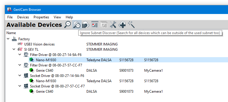
The GenICam Browser is used to detect connected devices via available Transport Layers and configure them.
GenICam Browser can be opened with:
All CVB GenICam core elements are represented in GenICam Browser:
After starting GenICam Browser for the first time, the available transport layer (TL), available interfaces and devices are listed in a tree view under Available Devices.
To search for available devices and to refresh the Available Devices tree use the Ignore Subnet Discover button. All available devices show up in Available Devices window. If you are using Linux, there are further actions to be taken. Please have a look at the Ignore Subnet Discover on Linux section.
Hardware relevant configuration steps have to be considered, refer:
GigE Vision
USB3 Vision
Other Transport Layer
Different camera symbol colors representing status information. Not displayed devices pointing to missing interface configuration. For details refer GenICam Browser User Guide in Help menu or hints in the GenICam Browser Logging window.


The Linux kernel usually filters broadcasts into wrong subnets. In order to spot cameras with an IP not matching the subnet of the NIC, this feature is essential though. Luckily you can turn the filtering off. Create a bash (.sh) file with following content and execute it.
Even though this may only last until the next reboot, it is good practice to enable the strict filtering again, after setting a valid IP, by writing a 1 to the config. Especially if your PC is connected to the internet or any other untrustworthy network!
Disabling the filter only for the NIC the camera is connected to in the first place is even safer:
For more information concern reading this introduction to Reverse Path Filtering.
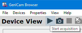
Doubleclick on the device (use Filter Driver in Windows and Socket Driver in Linux), which has a green camera icon now, or use the Open Device button to get a live view and to configure the device. The device will be opened in the Device View. On the left side a live image is shown, on the right side you will find the property grid to configure the device. In Available Devices the device shows up with an orange icon (device is open). In the Logging part of the application you get some detailed information. To get a single image use the Snap button, to start the acquisition press the Grab button and to stop the acquisition press the Stop button.

The GenICam driver options include communication and data handling parameters for GenICam. They should be set by your code as it is shown here:
The following table shows the GenICam driver options (example for GigE device). Note, that the name of the driver option indicated in the first column has to be used to set the option in your code.
| Driver Option | Settings which apply to all devices of that kind in the system |
|---|---|
| NumBuffer | Number of buffers allocated at vin startup: Acquiring images and using image processing functions with high CPU workload simultaneously can still lead to lost frames. Use the G2GetGrabStatus CVB-function to show the lost frames. To avoid lost images it is possible to increase the image buffer. In times of high workloads the images will be buffered. CVB takes the oldest image for processing. This principle just works for tasks where the high workload of the CPU is not steady so that CVB is capable of emptying the buffers from time to time. As a rule of thumb use as many buffers as the frames you acquire per second. Then the driver buffers one second. |
| PacketSize | Size of a data packet. For optimized performance adapt to NIC Jumbo Frame (Jumbo Packet) size. -1 = Default (1500 is used as packet size default value). 0 = Auto >1 = Set to value Can be used to reduce cpu usage. Attention: The network interface must also be configured to accept jumbo frames. Used switches in the network have to support jumbo frames also. |
| InterPacketDelay | Sets the delay between data packets. Adapt to NIC optimized Inter Packet delay. An increase in this delay can reduce the peak bandwidth of a device. 1 Use Default >= 0 Set to specified Value |
| AccessMode | The mode to open a device: 2 - Read Only: used when the device is slave in a Multicast setup (not controllable by application) 3 - Control : used when the device is the Multicast Master (controlled by application) 4 - Exclusive: peer to peer connection. This is the normal mode. 5 - Control with Enable Switchover: used when the device is the Multicast Master (controlled by application) and switchover should be enabled 6 - Control with Switchover Request: used when the application wants to take over the control of the device (switchover has to be enabled by another application and switchover key is required for authentication). |
| AttachChunk | Enable or disable chunk data. |
| PacketResend | Activate or deactivate the packet resend mechanism for the specific device. Since CVB 12.00.000 the packet resend is activated by default. |
| HeartbeatTimeout | This timeout controls how long the device waits for a signal from the application until it cancels that connection to that application. -1 Use Default >= 500 Set to specified value |
| MCMasterMode | 1 = Device is Multicast Master. If Master mode is choosen, AccessMode must one of the control modes, otherwise the driver will not load correctly. |
| MCSession | The IP Address of the Multicast session. |
| MCNoJoin | Multicast join (0) / no join (1). With join enabled (NoJoin = 0) the control device joins the stream. Set to 0 to get images on all devices. |
| UseTurboDrive | Enable (1) or Disable (0) Turbo Drive (for Dalsa cameras supporting this feature only). |
| SwitchoverKey | The authentication key (hexadecimal key 16bit unsigned) to take over control in Multicast switchover session. |
If you are using the deprecated GenICam vin driver, you may find additional driver options in the online documentation of CVB 14.0
User Sets
Every GenICam camera supports a functionality to save at least one User Set over the User Set Selector, i.e. a user exclusive camera features configuration. User configurations can be set and also be chosen to be the default configuration loaded when the camera is switched on with setting the Power-Up Configuration Selector.
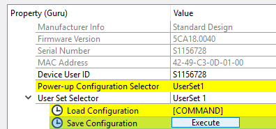
The factory configuration is not touched at all, such that restoring the initial settings at a later point in time is possible with Device Reset. 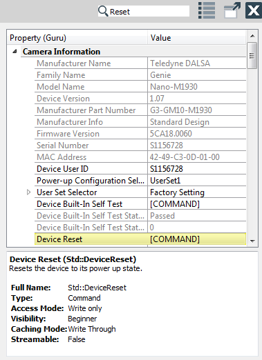
1) Define the destination directory:

2) Select the type:
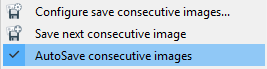
If activated new images are saved automatically to an *.emu file after starting the Grab. This should only be used with a continuous acquisition when the frame rate is very low. Otherwise the system is not able to save every image. Logging messages indicate lost images.
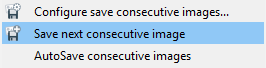
If activated new images are saved manually to a *.bmp file after starting the Grab.
Pixel Format Conversion
Converting images from Color cameras with bayer sensors
The conversion of an image’s pixel format can be necessary, if the captured image from the camera is acquire in a different format as the image is required for the application. Even though there is some automated adapted preprocessing, various source image formats, including Bayer formats (e.g. BayerRG8) are supported, so that they can be converted according to the user's purpose into different destination image formats (e.g. RGB8). Certain camera models (e.g. Dalsa Genie series) are capable of doing the conversion from within the camera, but the pixel conversion is recommended after the image transmission if the full efficiency of the camera is desired. An example for bayer conversiion can be found in Converting images from color camera with Bayer sensor below. More details on supported source and destination formats can be found here.
Debayering (conversion into RGB images) can be done with different methods, depending on the camera model and the drivers in use. It is not recommended to convert frames to RGB in cameras before transmission if the frame rate is extremely high. This is because raw Bayer requires only 8/10 Bit versus the 24 Bit necessary for RGB.
The Debayering operation can be performed in software after image transmission. This generally allows the greatest degree of flexibility and thus yields the best quality results (e.g. 3x3 debayering). The high performance CVB BayerToRGB tool has been developed to allow easy integration of this task.
In the GenICam User Guide for the deprecated vin driver, which can be found in the online documentation of CVB 14.0 other methods for debayering are described.