|
|
Common Vision Blox 14.1
|
|
|
Common Vision Blox 14.1
|
From the user's perspective, the GigE Vision standard consists of three parts:
Device Discovery
As this is a network protocol, devices must be found first. For this, the GigE Vision standard allows users to search for cameras in a sub-network. Cameras, in this case, play a passive part and respond to queries. The response to a query also contains information on the devices discovered, e.g., names and versions.
GVCP (GigE Vision Control Protocol)
The core purpose of the GVCP is the control of cameras on a register basis. An application reads out and writes individual data blocks. Every data block (register) represents one or several features such as the exposure time for the sensor.
GVSP (GigE Vision Streaming Protocol)
GVSP provides a protocol for streaming non-compressed and - since version 2.0 - also compressed data streams.
Due to overhead in the underlying ethernet communication it is not possible to reach the theoretical data rate of the network link. The reachable performance level and stability of a GigE Vision system strongly depends on the hardware and software components and their configuration.
Below and in the next chapters performance considerations and settings are described.
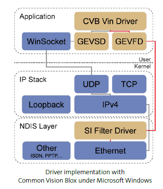
Due to the fact that the GigE Vision standard is a mere protocol description, generic driver implementations are possible. The simplest and most portable solution is to use the operating system IP network stack. This is often referred to as socket driver because all large operating systems provide the socket interface for network access (e.g. Windows Sockets or POSIX Sockets). However, normally this solution offers the poorest performance. Improvements are available by adopting the so-called high performance or filter drivers. Typical of both driver types is that they bypass the generic operating system network stack to provide better performance by specialised implementation. The driver runs in the operating system kernel and can therefore work on network data with the highest priority. Image data compilation already occurs in the driver and the image as a whole is transferred to the application. Because the network stack is bypassed, less CPU capacity is bound up and data security improves (fewer lost packages) due to the higher CPU priority. Even if the implementation of both driver types is different (driver directly for one network chip or generically for all network cards in the Windows filter stack), both offer the same improved performance for the protocol structure of GigE Vision.
Single camera on a dedicated NIC
The most simple setup is a single camera on a dedicated NIC (no other network traffic) with a point to point network connection. In order to retrieve their IP address, GEV cameras are configured to use DHCP by default and the same applies when configuring a NIC under Microsoft Windows. If there is no DHCP server (which is likely on a point to point connection) the camera and the NIC will, after a while, fall back to a mode called LLA. In this mode both ends (camera and host) will pick a random IP address. If you want to eliminate the time delay until they fall back to LLA you have to assign static IP addresses. In this type of scenario the bandwidth and data latency is optimal. Depending on which components are used and your system specification you can expect to get over 100MB/sec.
Single camera on a corporate Network
With a camera connected to a corporate network the scenario is only slightly different since a corporate network will usually have a DHCP server and both the camera and the PC will get their IP address from it. On the other hand, you cannot be sure that there won’t be other cameras on the network. In large set-ups there is a good chance that the system will address the wrong device. The bandwidth usage on such a system might be critical since it will affect the corporate network.
Multiple cameras on a single NIC
In this setup the IP address assignment is similar to the previous sections. The main concern in this case is the bandwidth. If in such a system the peak bandwidth is above one Gbit you have to make sure that either the switches can buffer enough data to sustain that peak or you have to limit the bandwidth of the cameras by setting the InterPacket delay of the cameras. The InterPacket delay is a mandatory bootstrap register of a GEV device. It can be set using the CV GenApiGrid Control (NodeMap) and then saving this to the profile of the camera to restore the setting on the next boot up. For most of the cameras this is controlled over the DeviceLinkThroughputLimit or StreamBytesPerSecond parameter.
Multiple cameras on multiple NICs
With multiple network interfaces you get better performance than with a single NIC but the IP-address assignment is a little bit more complicated. You have to make sure that each NIC is running on a separate subnet. If you have two NIC's running on the same subnet under windows, one cannot predict which NIC will be used to send the packet. If the packet is sent via the “wrong” NIC which is not connected to the correct camera, this camera will never see the packet and a connection will not be established.
The overall performance of a GigE Vision system setup depends on the network hardware components (network interface card, switch, camera, cable) as well as their appropriate configuration, which is described in the following chapters. Additionally to this there are some camera dependent GigE network features, which are described here.
TCP/IP Settings
Set the Camera IP address
Performance Settings
Firewall and VPN Settings
InterPacket Delay
Precision Time Protocol
siFilter Driver
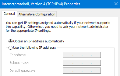
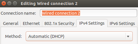
To establish a connection to any GigE Vision device, both the Network Interface Card (NIC) and the GigE Vision device must have a valid IP in the same subnet range. Addresses can be assigned both dynamically and statically.
| Windows: | Linux: |
|---|---|
|
|
| Windows: | Linux: |
|---|---|
|
|
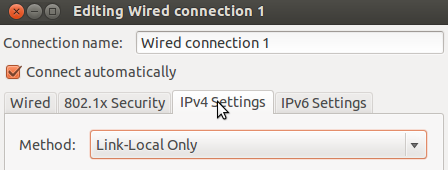
GigE Vision must be identified by an unique IP address. Addresses can be assigned both dynamically and statically. Per default, GigE cameras try to establish a connection to the host machine based on dynamic addresses. When plugged in, the camera first sends out a number of DHCP requests. If no answer is received within a fixed period of time (usually 60 s), the systems tries to auto configure the network via the LLA (Link Local Address) addressing scheme. LLA only works when both links are configured to be set dynamically (DHCP).
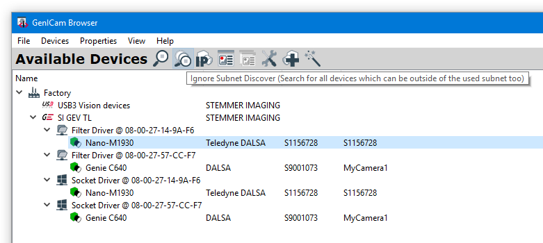
After starting GenICam Browser for the first time, the available transport layers (TL), available interfaces and devices are listed in a tree view under Available Devices. To search for available devices and to refresh the Available Devices tree use the Discover button. All available devices show up as green cameras. GigE devices are displayed under SI GEV TL:
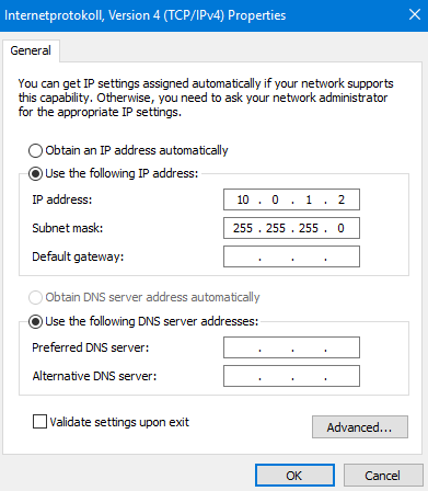
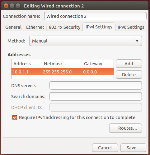
Static IP addressing is available in two different forms:
In both cases, the address must be set within the NIC and with an application interfacing the camera.
| Windows: Network and Internet, Network Connections | Linux: Network connections |
|---|---|
|
|
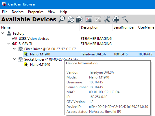
The camera may have another IP address configured or set as default. In the below example on the GenICam Browser the camera is found in another subnet (yellow icon). The camera IP address info can be read by left clicking the camera symbol or right mouse click -> Info. Access status here is NoAccess (Invalid IP).
Setting the IP address matching the NIC configuration is to be done over the configuration in Available Devices menu:
Force IP (fix over this power cycle):
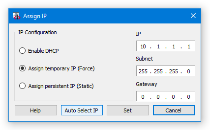
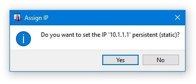
After each temporary IP setting it will be asked for storing it as static IP to keep the setting over restarts. Select 'No' in in case of temporary IP, valid for this power cycle. With 'Yes' the IP address is set as static.
Static IP (always fix):
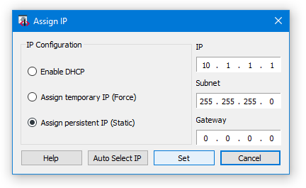
With both settings the camera icon has to be green with Access status: ReadWrite.
There are mandatory
which influence the performance of the system and the stability of the data transfer over the network card. This section will describe which settings should be optimized for maximum performance and minimal CPU usage. But it shows also which features can have massive impact in the stability of the data transfer. Wrong settings can result in a huge amount of lost packets that even whole images are discarded.
The variance of NIC performance settings depends on the used operating system and is described in detail in the following sections.
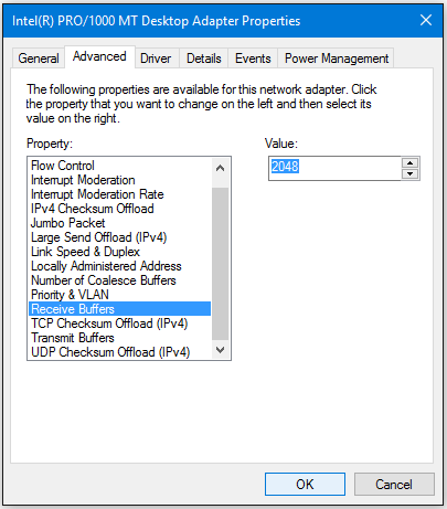
Receive Buffers
Sets the number of buffers used by the driver when copying data to the protocol memory. Increasing this value can enhance the receive performance, but also consumes system memory. Receive Descriptors are data segments that enable the adapter to allocate received packets to memory. Each received packet requires one Receive Descriptor, and each descriptor uses 2KB of memory.
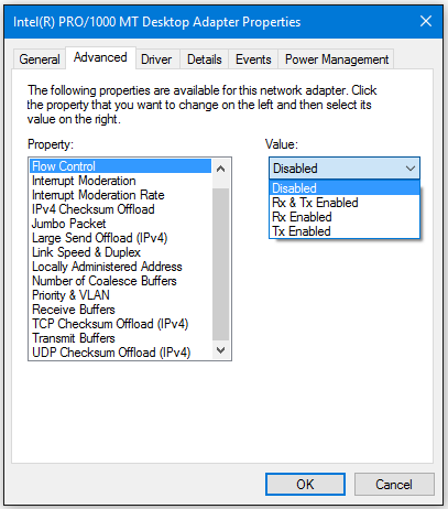
Flow Control
Enables adapters to generate or respond to flow control frames, which help regulate network traffic.
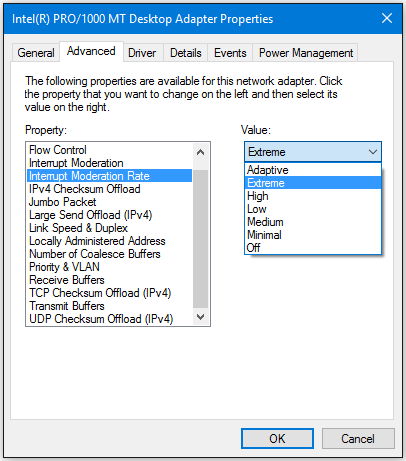
Interrupt Moderation Rate
Sets the Interrupt Throttle Rate (ITR), the rate at which the controller moderates interrupts. The default setting is optimized for common configurations. Changing this setting can improve network performance on certain network and system configurations. When an event occurs, the adapter generates an interrupt which allows the driver to handle the packet. At greater link speeds, more interrupts are created, and CPU rates also increase. This results in poor system performance. When you use a higher ITR setting, the interrupt rate is lower, and the result is better system performance. NOTE: A higher ITR rate also means the driver has more latency in handling packets. If the adapter is handling many small packets, lower the ITR so the driver is more responsive to incoming and outgoing packets.
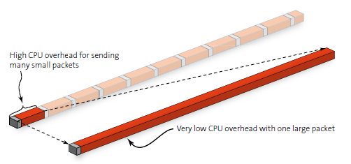
Jumbo Frames / Jumbo Packets
Enables or disables Jumbo Frame capability. If large packets make up the majority of traffic and more latency can be tolerated, Jumbo Frames can reduce CPU utilization and improve wire efficiency. Jumbo frames have a strong impact on the performance of the GigE Vision system. Jumbo frames are packages with more than the Ethernet MTU (Maximum Transmission Unit) of 1500 bytes. Less header data is transmitted, which allows more capacity to be available for user data.
Jumbo Frames can cause lost packets or frames when activated in the network card and the camera. But this is normally a side effect caused by the other settings mentioned before, which is only visible with Jumbo Frames. This means that, if you have trouble when using Jumbo Frames, try to find the cause in the previously mentioned settings instead of deactivating the Jumbo Frames.
Interrupt Throtteling (10 GigE only)
This parameter should be changed only if you observe performance problems with 10 GigE devices. Windows throttling mechanism Because multimedia programs require more resources, the Windows networking stack implements a throttling mechanism to restrict the processing of non-multimedia network traffic to 10 packets per millisecond.
To optimize the network card under Windows open the Network Properties Dialog (Start->Control Panel->Network Connections), right click on the network connection used. Select "Properties” from the context menu to get the Windows network configuration dialog. Depending on the network card driver, some of the settings described below may occur under a separate dialog page.
Receive Buffers
This parameter has to be set to the maximum available value. If it is too low you can loose huge amount of packets while streaming images
If your network card does not have this option you have to update your network card driver.
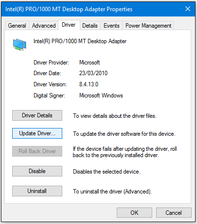
If it is not available with the newest driver use another network card.
Flow Control
This parameter has to be disabled. This feature regulates the network traffic which is something we do not want while streaming images.
Interrupt Moderation Rate
For this feature there are no general rules available which setting has to be used. It depends on the network card and the internal bandwidth of the system. If you want to have the lowest CPU load then you have to use the maximum value (Extreme). But with some systems we saw problems with this setting. Then you can loose packets or even whole frames. On some systems also low values can cause these problems. If you have problems with lost packets or lost frames, change this setting to Off. This is the most secure setting - but also the setting with the highest CPU load.
Jumbo Frames / Jumbo Packets
Jumbo Frames are necessary when the maximum network bandwidth is needed. E.g. when using a fast camera or a high resolution camera. Because of this the recommendation is to always use Jumbo Frames when possible.
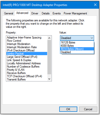
NOTE: When activated in the network card this does not mean that Jumbo Frames are used. This only means that the network card can handle Jumbo Frames.
To really use Jumbo Frames this has to be activated in the camera by setting the packet size to the appropriate value. This has to be done via the driver options. The appropriate value depends on the maximum available packet size in the camera and the maximum setting in the network card. As recommendation use 8192 as PacketSize if supported by camera and network card, it was used very often without problems. Normally, if Jumbo Frames are disabled, this does not cause problems with lost packets or lost frames. But as the camera is not able to send the images as fast as they are acquired from the sensor you can have a visible delay in the live image. On the other hand Jumbo Frames can cause lost packets or frames when activated in the network card and the camera. But this is normally a side effect caused by the other settings mentioned before, which is only visible with Jumbo Frames. This means that if you have trouble when using Jumbo Frames try to find the cause in the previously mentioned settings instead of deactivating the Jumbo Frames.
Interrupt Throtteling (10 GigE only)
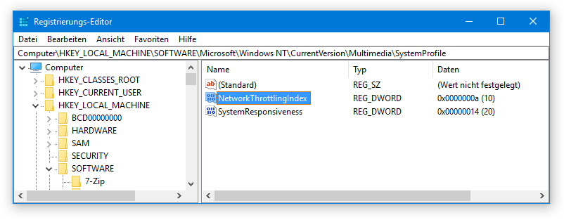
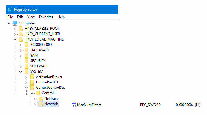
The throttling will come into effect only when you are running multimedia programs that are time sensitive. However, this throttling mechanism can potentially cause a decrease in network performance during the active multimedia playback period. This decrease in performance is likely to occur only on high speed networks that are saturated to maximum capacity. By default, the value for the NetworkThrottlingIndex registry entry is set to 10.
Refer Registry entry:
HKEY_LOCAL_MACHINE\SOFTWARE\Microsoft\Windows NT\CurrentVersion\Multimedia\SystemProfile\
Name: NetworkThrottlingIndex
Value type: DWORD
Value data: From integer 1 through integer 70 (Decimal) (Decimal)
When the NetworkThrottlingIndex registry entry does not exist, the behavior resembles the default behavior. Network throttling can be completely turned off by setting the value to FFFFFFFF (hexadecimal). You must restart the computer after you make a change to the value of the NetworkThrottlingIndex registry entry.
To optimize the network card under Linux open the Network Connections Dialog or with direct terminal commands. Using the dialog window the "Wired connection x” from the list has to be selected and the "Edit" button to has be used.
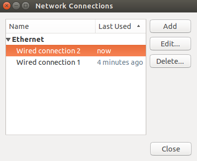
Depending on the network card driver, some of the settings described below may occur under a separate dialog page.
Receive Buffers
This parameter has to be set to the maximum available value. If it is too low you can loose huge amount of packets while streaming images. To change the Receive Descriptors on Linux you need to download ethtool from the installed packet manager.
Get Descriptor Information from eth2: > sudo ethtool -g eth2
Set Receive Descriptors of eth2 to 2048: > sudo ethtool -G eth2 rx 2048
Jumbo Frames / Jumbo Packets
Jumbo Frames are necessary when the maximum network bandwidth is needed. E.g. when using a fast camera or a high resolution camera. Because of this the recommendation is to always use Jumbo Frames when possible.
for eth2 set: > sudo ifconfig eth2 mtu 8192 up or with the dialog:
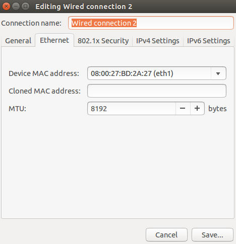
NOTE: When activated in the network card this does not mean that Jumbo Frames are used. This only means that the network card can handle Jumbo Frames. To really use Jumbo Frames this has to be activated in the camera by setting the packet size to the appropriate value. The appropriate value depends on the maximum available packet size in the camera and the maximum setting in the network card. As recommendation use 8192 as PacketSize if supported by camera and network card, it was used very often without problems. Normally, if Jumbo Frames are disabled, this does not cause problems with lost packets or lost frames. But as the camera is not able to send the images as fast as they are acquired from the sensor, you can have a visible delay in the live image.
A detailed description of the configuration of the Jumbo Frames/Packes can be found in the online documentation of CVB 14.0).
Firewalls can block GigE Vision packets and slow down the system performance. Therefore it is important to disable all firewalls within the camera connection setup when there are connection problems.
The following steps are necessary to switch off the Windows software firewall. For Linux there is no configuration necessary. If you have a hardware firewall (which is available on some NICs) disable those firewalls also.
Also any VPN software running on the system may contain a "Stateful Firewall" which is active even if no tunnel is established. This firewall will block traffic from the camera. In order to work with GEV devices and depending on the VPN software you use, you have to disable your VPN software.
Windows only:
1) Open the Firewall Customize Settings dialog (Start -> Control Panel -> Systems and Security -> Windows Firewall -> Turn Windows Firewall on or off):
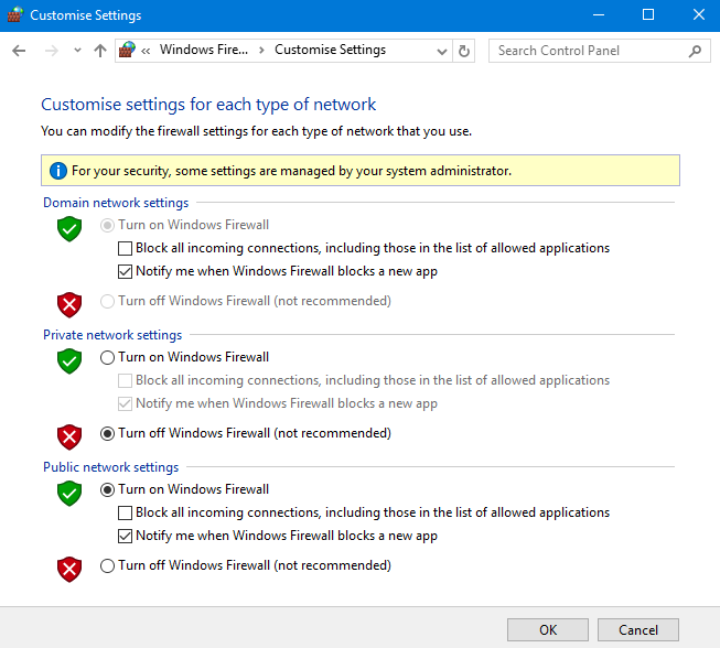
2) Select the "Turn Off Windows Firewall" option to disable the firewall for the type of network which is used for the camera connection.
3) Close all dialogs with the "OK" button to apply the changes.
 Consider the settings from GigE Vision -> Network Configuration chapter first.
Inter Packet Delay is a parameter to control the data rate from cameras. It is important in multi-camera scenarios.
With Inter Packet Delay cameras can be slowed down while acquisition by adding delays between the sent packets. Other devices are able to send data then too. Inter Packet Delay together with Frame Rate settings and Exposure Time is important as soon as you connect multiple cameras to one network port exceeding together the maximum data rate. Gigabit Ethernet provides 1 Gb/s (Gigabit per second) Bandwith ~ 100 MB/s (Megabytes per second) assuming an optimal network hardware and configuration. In such a system you may have to limit the bandwidth of the cameras by setting the frame rate and the Inter Packet Delay.
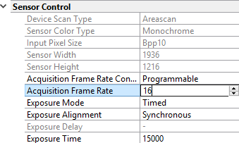
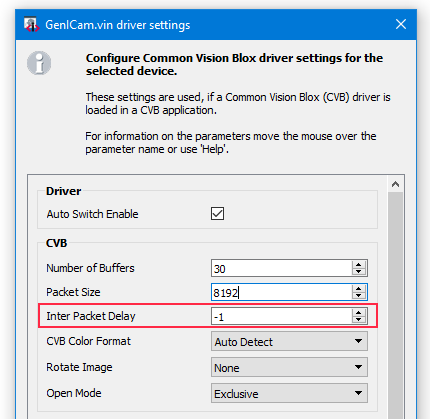
If the optimum between Inter Packet Delay and Acquisition Frame Rate is determined, the setting has to be saved in the device options.
Use the Device Options (Driver Options for the selected device) dialog window in GenICam Browser :![]()
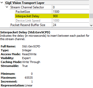
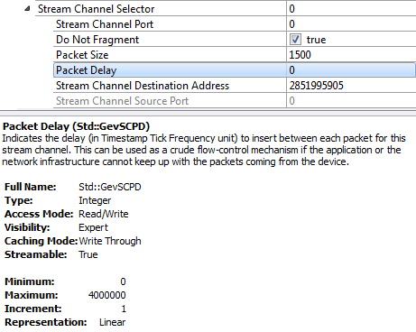
Adding a packet delay between packets during transmission is always based on GenICam Transport Layer Control feature GevSCPD but the representation in camera NodeMaps may differ.
In the following there are some examples how to find the feature.
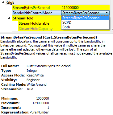
AV GigE example:
They have a feature called "BandwidthControlMode" which is set to "StreamBytesPerSecond" by default. With "StreamBytesPerSecond" the bandwidth which is used by a camera can be changed directly in bytes per second. (e.g. 2 cameras -> StreamBytesPerSecond / 2)
DALSA GigE example:
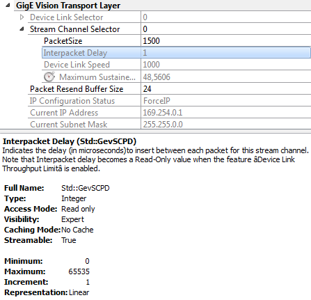
JAI GigE example:
Precision time protocol for synchronising several cameras in an Ethernet network
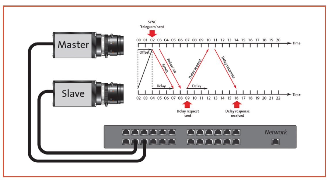
The Precision Time Protocol (PTP) IEEE 1588 enables the exact cycle synchronisation of several devices in an Ethernet system. When the clocks of the devices such as cameras, PCs and sensors, are synchronised, future software image triggers can be synchronised within 2 μs. The GigE Vision 2.0 standard has incorporated PTP IEEE 1588 and warrants maximum compatibility between machine vision hardware and software suppliers in future.
Synchronisation of several cameras cameras supporting PTP are put in a special PTP mode which manages and defines the synchronisation of the camera clocks. The device clock of the master is output with the timestamp of the camera and synchronises several cameras. When the PTP mode is set to 'master', 'slave' or 'auto', the camera synchronisation starts in the network, provided one device is configured as master.
The process starts with the "master" camera which sends a "sync" message via multicast messaging. The "slave" camera calculates the time difference between its internal cycle and that of the master camera. In addition, Delay Request Message (by the slave) and Delay Response Message (by the master) are sent to synchronise the slave clock with the master cycle. When the time difference of the clock is ≤2 μs, the cameras are in synchronous mode. In addition to the exchange of synchronisation messages, the clocks are constantly readjusted by filters and statistical methods in order to eliminate deviations due to the physical layers, the network, repeater or switch.
Configure Cameras supporting PTP
Settings in Property Grid (consider camera specific parameter name variance):
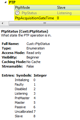
Wait until GigE -> PTP -> PtpStatus has changed from Syncing to Slave. Start acquisition on both cameras.
Set on both cameras the GigE -> PTP -> PtpAcquisitionGateTime to a higher value than GigE -> Timestamp -> GevTimestampValue (get the current GevTimestampValue with GigE -> Timestamp -> GevTimestampControlLatch).
Ensure, that PtpAcquisitionGateTime is still in future after setting on both cameras.
Acquisition stops on both cameras, when PtpAcquisitionGateTime is reached, the cameras run synchronous.
Example: PTP parameter in Nodemap of Dalsa camera
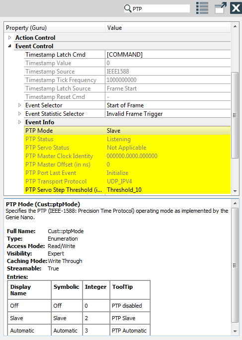
Example: PTP parameter in Nodemap of AV camera
Windows only
The siNetFilter Driver for GigE Vision technology is used to bypass the standard network stack (used by the operating system) for all data stream packets. It filters GigE Vision related data packets and transfers them directly to an application-provided data buffer. This greatly reduces the CPU load of the system. All non GigE Vision data stream related packets are unaffected.
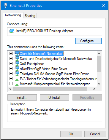
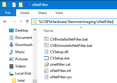
Basically all CVB installations contain the siNetFilter Driver for GigE Vision. (refer %CVB%Hardware/StemmerImaging/siNetFilter)
Under certain circumstances it could be necessary to uninstall / reinstall / update / disable or enable the GigE Vision Filter Driver. Each NIC counts as one siNetFilter Driver, other Filter Driver maybe installed without recognition, e.g. through VBox, VPN, etc. - so maximum has to be increased.
If you have uninstalled the siNetFilter Driver you can reinstall it.
1) Open your Network Properties Dialog (Start -> Control Panel -> Network Connections) right click on the network connection used.
Select "Properties" from the context menu to get the network configuration dialog.
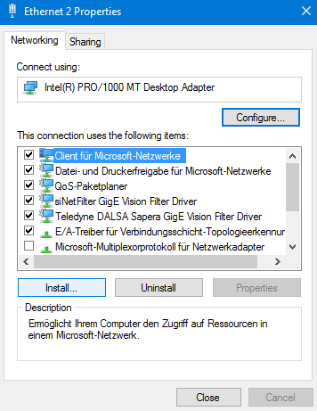
2) Click the "Install" button to open the following dialog.
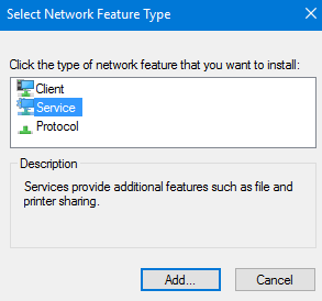
3) Select "Service" and click the "Add" button.
4) Select the siNetFilter Driver and click the “OK” button.
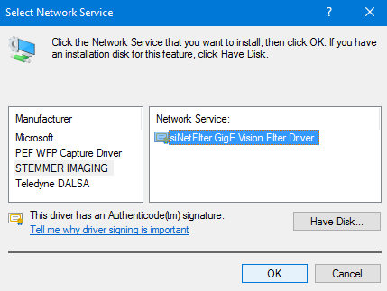
5) The setup will now try to install the siNetFilter Driver.
Press the "Proceed with Installation" button to install the driver for all NICs.
It may appear several times depending on the number of NICs in your system.
6) Close all dialogs with the "OK" button to apply the changes.
To update the siNetFilter Driver these steps are necessary.
1) Open you Network Properties Dialog (Start -> Control Panel -> Network Connections) right click on the network connection used.
Select "Properties" from the context menu to get the Windows network configuration dialog.
2) Click the "Install" button to open the following dialog.
3) Select "Service" and click on the "Add" button.
4) Click the "Have Disk" button.
5) Click the "Search…" button and the "Browse..." button in the next window.
6) Select the destination directory which contains the siNetFilter Driver and select the *.inf file.
Click the "Open" button to proceed.
7) Click the "OK" button to proceed.
8) Press the "OK" button in the next dialog.
9) The setup will now try to install the siNetFilter Driver. Press the "Proceed with Installation" button to install the driver for all NICs. It may appear several times depending on the number of NICs in your system.
10) Close all dialogs with the "OK" button to apply the changes.
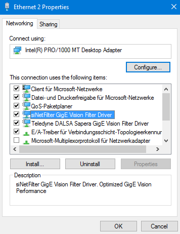
Following steps are necessary to disable the driver for a specific NIC. You must repeat these steps for each NIC for which the GigE Vision siNetFilter Drivers need to be disabled. Disabling the Filter Driver does not count down the maximum number of Filter Drivers configured on your system.
1) Open you Network Properties Dialog (Start -> Control Panel -> Network Connections) right click on the network connection used.
Select "Properties” from the context menu to get the Windows network configuration dialog.
2) Uncheck the check box for the siNetFilter Driver.
3) Close all dialogs with the "OK" button to apply the changes.
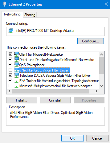
When you disabled the siNetFilter Driver for a specific NIC you can enable it again.
1) Open you Network Properties Dialog (Start -> Control Panel -> Network Connections) right click on the network connection used. Select "Properties" from the context menu to get the network configuration dialog.
2) Check the check box for the siNetFilter Driver.
3) Close all dialogs with the "OK" button to apply the changes
To uninstall the siNetFilter Driver on all NICs follow these steps.
1) Open you Network Properties Dialog (Start -> Control Panel -> Network Connections) right click on the network connection used.
Select "Properties" from the context menu to get the network configuration dialog.
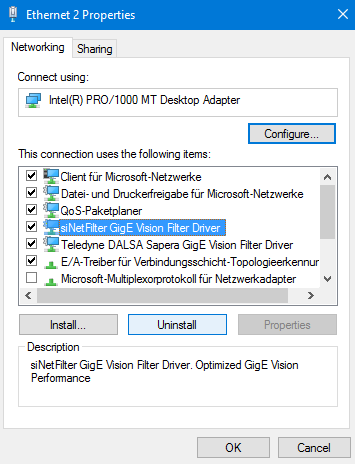
2) Select (not uncheck!) the siNetFilter Driver.
3) Press the Uninstall button and follow the instructions (it might be necessary to reboot the system afterwards).
4) Close all dialogs with the "OK" button to apply the changes.
What's the difference between GigE and GigE Vision?
What is a filter driver?
Is it possible to use wireless networks to transfer my image data?
Is it possible to use Multicast with GigE Vision?
Is GigE Vision IPv6 ready?
Can I connect more than one camera per network interface?
Why doesn't GEV use QOS (quality of service) to control the flow of data?
What's the CPU load caused by GigE Vision?
What is the maximum performance of one GigE NIC?
What is the data latency compared to a frame grabber?
What is the round trip time on a GEV setup?
UDP is a "not reliable" protocol. Why is UDP used?
How fast is the control protocol?
Is GigE Vision applicable to just cameras or could it be used for vision related peripherals like Lighting and timing controllers?
Can a GigE Vision device be simulated in software to enable fast data transfer between different computers?
Can I use multiple filter drivers for one NIC?
Can I change the order in which the filter driver is placed into the driver stack?
Can I use network analyzer software on my GigE Vision system?
Can I use software VPN on my GigE Vision system?
Which software packages are known to cause problems on a GigE Vision system and how can I solve those problems?
Can I optimize my network card for GigE Vision?
I can adjust the size of the receive descriptor list on my NIC. What does that mean?
I can adjust the interrupt rate on my NIC. What does that mean?
Which network ports are used by GigE Vision?
GigE means Gigabit Ethernet and is the general Ethernet network technology combined with the bandwidth specification Gigabit. GigE Vision (GEV) is the name of a network protocol, optimized for machine vision, maintained by the AIA (Automated Imaging Association) designed to control machine vision devices (cameras) and to transfer their data (images) as effectively as possible across IP networks. Although GigE Vision contains GigE in its name, the protocol also works on lower bandwidth, although at least GigE is recommended.
A filter driver is a kernel-mode driver which normally resides between the upper-level protocol and the lower-level miniport drivers (on a Windows based system). For GigE Vision technology it is used to bypass the standard network stack (used by the operating system) for all data stream packets. It filters GigE Vision related data packets and transfers them directly to an application-provided data buffer. This greatly reduces the CPU load of the system. All non GigE Vision data stream related packets are unaffected.
In principle there is no problem running a GEV camera over a wireless connection. The problem here is one of reliability. Wireless networks dynamically adjust their speed depending on the connection quality. This means that if the connection quality suddenly drops for some reason, a lot of packets will be dropped on the network. This leads to an avalanche of resend requests from the host (which did not receive the packets) and in the worst case scenario, this will cause the whole connection to the camera to fail. So, in principle, yes it will work but it is neither guaranteed or recommended.
The short answer is YES. The long answer is: Multicast is a Layer 3 IP protocol implementation. GEV is on Layer 4 so in general GEV will simply use the different IPs associated with Multicast ranges. The question is, whether the hardware (switches) and the software you are using supports it. CVB did not support Multicast from the first version on but in further releases. Please refer to the actual specific GenICam Driver Release Notes.
It is prepared but not yet implemented. All points where IPs are stored in the device are prepared but are not part of the current standard.
Yes, the number of cameras that can be connected to a single NIC is not limited in practice. So it really depends on bandwidth and latency, and hence no general answer. The more cameras you connect the more you have to think about peak bandwidth and latency.
One reason is that QOS with IPv4 is cooperative between the connected devices. It is not necessarily reliable or even forced as it is with other technologies. This might change in Ipv6 once that is supported. The other problem with QOS is that one cannot really predict the bandwidth that a triggered camera might use. There might be a peak bandwidth of 1 gpps one moment, while in the next second there might be no transfer for one minute! Also, with GigE you are not limited to a specific number of cameras you can connect. You could have 100 cameras all triggered at the same time but only once per minute. How would you share their bandwidth? What has been implemented however is a mechanism called inter-packet delay. This puts a small delay between the sending of packets which enables you to limit the bandwidth of a single camera and leave it to the switch to buffer and serialize the data from multiple cameras.
This really depends on the system you use, the bandwidth of the camera, the packet size, the driver software and the performance of your network components. The new multi-core CPUs are ideal for GEV because the operating system can distribute the load among them.
Depending on your system configuration you can stream above 100MB/s sustained through one NIC. That does not mean that you can easily extrapolate this to two, three or four NICs. If you have applications close to that limit it is recommended that you contact the technical support of STEMMER IMAGING respectively your local distributor.
The short answer is: That depends on the system. The long answer is more difficult. It really depends on the camera in use, the network setup, the packet size, the PC and the system load. Assuming the camera is connected directly (no switch or router, no lost packets on the network) and with almost no CPU load on the receiving system, the latency is in the µs region. Every switch would add to that (again depending on the switch) probably in the lower µs range. But all this is a simple delay and is relatively easy to handle since it is the same with every image. The worst situation is a jitter in the arrival of images depending on the transmission quality and on the system load. If you have to perform a resend with a GigE camera, this adds to the data latency which is not predictable.
To measure a roundtrip time we used a camera which indicated the end of frame transfer in the camera by a digital output signal. We triggered an image in the camera and as soon as the application reviewed the complete image it set another digital output signal in the camera. We measured the delay between the two signals with an oscilloscope. Once again, the time depends on various factors. We measured a roundtrip time of about 3.5 ms. This gives a realistic estimation on what such a delay would be in a real application.
That is true, but this is the reason why we have GEV. Since UDP is a connectionless protocol and since it does not have mechanisms to cope with lost packages we put a protocol layer on top so that we take care of these weaknesses while still maintaining the optimal performance at the lowest possible integration costs. We chose UDP instead of TCP because of performance and cost reasons.
On an average system it takes between 0.5 ms and 2 ms (depending on the device and the network setup) to write a GEV register from the issue of the Write Reg command until the PC has the acknowledge. This timing is for a direct link.
Please also refer to the following FAQ's:
Devices which don't need to stream data can simply use the control protocol only and not expose a streaming channel. In this way GigE Vision can be used as a simple control protocol.
Yes of course it can. Since GigE Vision uses standard network protocol mechanisms it can be implemented in software on the host. Common Vision Blox provides the GigE Vision Server tool for this very purpose.
The GigE Vision Server tool allows you to start an application on your local PC or embedded device that behaves just like a regular GigE Vision device in your local network (i. e. the tool will react to broadcasts and implement all the logic necessary to open the virtual device generated by the application and interact with it like if it were a camera by accessing its node map or streaming images.
Furthermore, this software-generated virtual device can be endowed with a user-definable node map; this means that the behaviour of the virtual device can be defined to a great extent in software and the implemented behavior can be tapped into by the software that opens the virtual device. As and example it would be possible to create a virtual device with selectable preprocessing of the streamed images and the client software opening the virtual device can then configure the preprocessing based on its current needs using regular GenICam node map access.
You can use more than one filter driver for one NIC e.g. if you have SDK's or GigE Vision devices from several vendors on a single system. The maximum number of filter drivers for one NIC is limited. There is one major drawback using multiple filter drivers on a single NIC. Assume you have installed 2 filter drivers from 2 different vendors. You have a GigE Vision device from each vendor which is processed by the filter driver of that vendor.
Your network stack will normally look something like this:
PROTOCOLDRIVER (upper-level)
FILTERDRIVER_B
FILTERDRIVER_A
MINIPORTDRIVER (lower-level)
NIC
Device_A + Device_B
All data stream packets from Device_A are filtered in FILTERDRIVER_A.
All data stream packets from Device_B are filtered in FILTERDRIVER_B.
But all data stream packets from Device_B have to pass FILTERDRIVER_A before they are processed by FILTERDRIVER_B.
This will cause additional CPU load. The more drivers you have in the stack the more CPU load you will get. You can use different filter drivers on different NIC's. without causing additional CPU load when you disable (not uninstall) the unused driver for this NIC.
No you can not. This is controlled by the operating system. You can not select which driver is lower or higher in the stack.
You should not. If you use a network analyzer software like Wireshark on your GigE Vision system you might run into problems. Wireshark for example uses the WinPCap kernel mode protocol driver to analyze all incoming and outgoing packets. Depending on the order in which the operating system has installed the filter drivers and WinPCap in the network stack, your filter driver might not receive any GigE Vision data stream packet. In that case you will get no GigE Vision data!
You should not. We have seen problems e.g. using VPN software from Cisco. There are similar reasons for this as mentioned under FAQ Can I use network analyzer software on my GigE Vision system?
VPN Software e.g.: Cisco VPN (Solution: disable network service called Deterministic Network Enhancer + Stop VPN service with "net stop cvpnd") Network Analyzing Software like Wireshark (Solution: uninstall WinPCap)
See also FAQ's Can I use network analyzer software on my GigE Vision system? and Can I use software VPN on my GigE Vision system?
Yes you can. The optimization depends on the hardware you are using. So bear in mind that you should always use the proper hardware.
Please have a look at our recommendations for the Performance Settings.
This sets the number of buffers used by the NIC driver that are used to copy data to the system memory (normally done with DMA). Increasing this value can enhance receive performance, but also consumes system memory. Receive descriptors are data segments that enable the adapter to allocate received packets to memory. Each received packet requires one receive descriptor, and each descriptor uses certain amount of memory. If the number of receive descriptors is to low than the NIC might run out of memory which will cause packet loss. For GigE Vision this might cause a lot of packet resend requests.
Depending on the NIC you are using, you can decrease the number of interrupts generated by the NIC. This has some influence on the CPU load. On a INTEL Network Interface Card you can decrease the number of interrupts that are generated by setting the "Interrupt Moderation Rate" to "Extreme". For other network cards there are similar ways of decreasing the interrupt rate.
GigE Vision consists of a control and a streaming part. Only the control connection is claiming a static port on the device end (UDP 3956), which is also registered with IANA. The control connection source port as well as the streaming connection port(s) are dynamically allocated from the ephemeral port range 49152 through 65536.