|
|
Common Vision Blox 14.1
|
|
|
Common Vision Blox 14.1
|
In this document you will find detailed background information about the GenICam standard, transport layers and the CVB driver structure.
The GenICam™ standard (Generic Interface for Cameras) provides a generic software interface for any kind of vision acquisition devices, independent of their hardware interface. It allows access to devices such as cameras or strobe controllers via a standardised interface, no matter which technology such as GigE Vision, CameraLink, CameraLink HS, CoaXPress or USB3 Vision-is used.
The GenICam standard consists of different modules, each addressing a specific part of a typical vision system:
For more information refer the EMVA homepage: http://www.emva.org/standards-technology/genicam/
Compared to manufacturer specific SDKs Common Vision Blox with GenICam offers manufacturer independence and increased image acquisition functionality. Hardware compatibility is accomplished by supporting various acquisition technologies including any GenICam GenTL provider (transport layer). Being the GenICam GenTL standard maintainers we can assure best support for compliant GenTL providers.
Attention: With Common Vision Blox 13.3 the GenICam.vin driver interface has been extended by the new GenTL acquisition interface. This document will only describe the new GenTL interface. If you are still using the GenICam.vin, you will find a detailed description online documentation of CVB 14.0.
| CVB Image Manager SDK | ||
| GenICam GenTL Consumer | ||
| GigE Vision GenTL Producer | USB Vision GenTL Producer | 3rd Party GenTL Producer |
 | ||
The following acquisition device interface standards are generally used for new applications:
For cameras to connect directly to a PC:
Supported Operating systems and other system requirements for the GenICam driver
For more details please refer to Release Notes chapter.
If possible use the newest CVB version because of many improvements in the GenICam package.
The GenICam driver options are described in the section Persistent Settings in GenICam Driver and should be set by your code. If you are using the deprecated vin driver, you can also set the option with the GenICam Browser (for further information about the deprecated vin driver got to the online documentation of CVB 14.0).
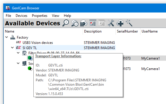
Information about all supported Transport Layers (*.cti files) can be found in the GenICam Browser in the Available Devices window. In this example the STEMMER IMAGING CVB USB3 Vision (CVUSBTL) and the GigE Vision Transport Layer (GEVTL) are available.
For detailed information, please refer to:
GigE Vision
USB3 Vision
Other Transport Layer
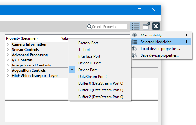
A nodemap displayed in the Property Grid is part of the Transport Layer and therefore available for all GenICam compliant cameras. Nodemaps are based on the acquisition hardware *.xml file and structured in different ports:
DevicePort
DeviceTLPort
DataStreamPort
FactoryPort
InterfacePort
TLPort
If the device has no *.xml file in its memory a "Nodemap unavailable" message is returned when the device is opened. Be aware that setting a correct XML file for the device is a precondition, if there are problems, refer trouble shooting section.
For Parameter Reference refer to GenICam Standard, SFNC (Standard Features Naming Convention) part.
Get access to the nodemaps in your code:
Get access to the nodemaps via GenICam Browser:
This is the port, which contains the nodemap for the device (remote device). It is the normal nodemap for all device features and is used by default.
In the CVB getter function for nodemaps it is referenced with Device.
This is the port, which contains the nodemap for the device module of the GenTL. The device module represents the GenTL Producers' proxy for one physical remote device. The responsibility of the device module is to enable the communication with the remote device and to enumerate and instantiate data stream modules. The device module also presents signaling- and module configuration capabilities.
In the CVB getter function for nodemaps it is referenced with TLDevice.
This is the port, which contains the nodemap for the Data Stream module. A single (image) data stream from the device is represented by the Data Stream module. The purpose of this module is to provide the acquisition engine and to maintain the internal buffer pool. Beside that the Data Stream module also presents Signaling and module configuration capabilities.
In the CVB getter function for nodemaps it is referenced with TLDatastream.
Sample Code in C++: CameraConfig example
In the following two section nodes for buffer handling control and statistic nodes are described in detail.
This is the port which contains the NodeMap for the Factory.
In the CVB getter function for nodemaps it is referenced with TLFactory.
This is the port which contains the NodeMap for the interface module. An interface module represents one physical interface in the system. For Ethernet based Transport Layer technologies this would be a Network Interface Card (NIC), for a Camera Link based implementation this would be one frame grabber board. The enumeration and instantiation of available devices on this interface is the main role of this module. The interface module also presents signaling and module configuration capabilities.
In the CVB getter function for nodemaps it is referenced with TLInterface.
python Code Example: DeviceConfiguration example
Action Control allows sending "action signals" over ethernet to one or multiple devices in the network to trigger specific configured actions in the device.
Please refer to the manual of your camera for more information on how to setup Action Control for your needs.
This is the port which contains the NodeMap for the system module. For every GenTL Consumer the system module as the root of the hierarchy is the entry point to a GenTL Producer software driver. It represents the whole system (not global, just the whole system of the GenTL Producer driver) on the host side from the GenTL libraries point of view. The main task of the system module is to enumerate and instantiate available interfaces covered by the implementation. The system module also provides signaling capability and configuration of the module's internal functionality.
In the CVB getter function for nodemaps it is referenced with TLSystem.
Unlike previous nodemaps, such as DeviceTL nodemap, the VinDevice nodemap and VinBuffer nodemap are not displayed in the property grid, even though they are available for all GenICam-compliant cameras. These parameters can be individually tuned by users, enabling them to customize camera settings to their liking.
This user nodemap aims to configure the device and its corresponding driver settings. A user can read and adjust parameters of a device opened through CVB in the 3rd acquisition stack (GenTL) only. The nodemap includes features related to TurboDrive and chunk data transmission.
The following list describes all available nodes:
The VinBuffer nodemap provides means to gather information about a single buffer returned by the stream wait function. It is - also - only available in the 3rd generation acquisition stack (GenTL).
The following nodes are retrievable through the nodmap:
Here is an example of how you might use the VinDevice to check the activation of TurboDrive and VinBuffer nodemap to check for indication of a corrupt buffer:
A GenICam device is always equipped with a certain version of firmware. Every firmware revision has a dedicated XML file to describe the abilities and features of the device. When opening a camera its XML file is going to be read when the device is plugged in for the first time. The downloaded structure serves as the base for the property grid (Nodemap).
To set a new XML file, run the EditBindings console application. With this console application you can see the current linked *.xml file and you can add/delete/bind a new XML file. For future access to the device, the XML file is saved within a database on the host machine and loaded automatically whenever the camera is connected. Camera xml files for Common Vision Blox are saved under %CVBDATA%GenICam\xml\Registry\Files (Windows) and /var/opt/cvb/GenICam/xml (Linux). It is possible that an XML file is changed over time by the vendor to simplify the interface, while the firmware remains the same. It then suffices to set the new XML file with the CVB EditBindings application since the internal functionality remains the same. In case a new revision of camera firmware is published, it is generally distributed by STEMMER IMAGING with further remarks about the changes made as well as the installation procedure. If you don't find an appropriate update please contact our technical support.
If something is GenICam compliant does it need to be GigE Vision Compliant?
The camera is not seen in the GenICam Browser
I can open the camera in the GenICam Browser but get a white picture
I can open the camera in the GenICam Browser but get a flickering picture
Image contains a logo or is complete grey
Error message: Nodemap unavailable
I get a large number of lost frames
The acquired images show defects
I can acquire images but the GigEVision events from the camera are not fired
GigE Cameras disappear in the GenICam Browser
Occasionally Time Out errors when performing image acquisition with Software Trigger
How can I discard corrupt frames in the driver?
How can I find the installed transport layer ?
GenICam is frequently called the compatibility layer. A device which is GigE Vision compliant must by definition also be GenICam compliant since GigE Vision and USB3 Vision has a mandatory reference to GenICam. So in a way the use of the GenICam layer is what distinguishes GigE Vision and USB3 Vision from plain GigE/USB3. The reverse, however, is not the case: GenICam may in principle also be applied to other transport technologies.
Note, by the way, that the "Vision" bit in "GigE Vision" and "USB3 Vision" has lower-level implications as it defines the expected format of the packets sent back and forth on the physical infrastructure.
For GigE Vision make sure the IP addresses of both the camera and the NIC the camera is connected to, are on the same subnet,if you have multiple NIC's in the system make sure they don’t share the same subnet's. Otherwise this can result in unpredictable behavior. Refer GigE Vision checklist.
For USB3 Vision please ensure that USB 3.0 ports are used and all other hardware requirements are fulfilled. Refer USB3 checklist. Seldom it could be necessary to delete the GenIcam XML file and directory manually: %CVBDATA%GenICam and start the application again. For all other vision hardware components (cameras, grabber) ensure that the necessary software and driver is installed.
Change the Display Engine type from OpenGL to Raster. Display Engine can be changed only if no device is open. If the selection is disabled, all devices must be closed.
This can occur with high performance cameras or multi-camera scenarios which are producing pictures with a higher bandwith than the communication link is able to transfer (GigE Vision, USB3 Vision).
Cameras transfers empty pictures as soon as a bottleneck is detected. This can be observed with the flickering effect on freerun pictures in CVB and watching the Data Stream Port statistic values. Exposure time adaption, Framerate decreasing to a value matching the transfer capabilities and optimizing the network configuration for GigE hardware should solve the problem.
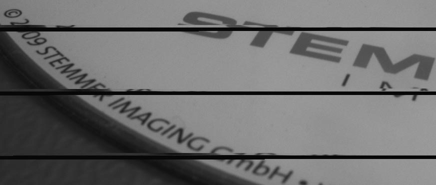
If the cameras are not licensed via CameraSuite or any other valid Image Manager license like a dongle, a Node-locked or Triallicense there are sent some kind of distorted images. This could be either a logo as a watermark in the left top part of the image:

or that grey images with a grey value of 128 appear from time to time. Additional there appears a red text overlay in the display which says " Common Vision Blox evaluation".
If the device has no XML file in its memory "Nodemap unavailable" message is returned when a device is opened. Be aware that setting a correct XML file for the device is a precondition - so it has to be (re)generated. Availability, version and binding information of a camera GenICam XML-file can be checked with the EditBindings application. Sometimes it could be necessary to backup and delete the GenIcam XML file and directory manually: %CVBDATA%GenICam and start the application again.
Check the hardware components and configuration if they inter-work with the camera configuration and capability. Most problems are caused due to unsatisfactory performance.
If sections of the acquired images are missing or random noise is visible, the reason is probably a transmission problem. The following image shows an example of this type of transmission problems:
Maybe you see black lines or lines with old image data. Check the hardware components and configuration if they inter-work with the camera configuration and capability. Please refer the corresponding chapters in this User Guide for optimization.
Disable the firewall. Enable the events with the EventNotification feature.
The system was already working and without changing anything the GigE camera does not appear any more in the GenICam Browser. But it is possible to PING the camera. Means IP configuration and camera is OK. Solution: Please delete the following file in the CVB Root path ..\Genicam\Registry\xml\db.xml Restart the CVB GenICam Browser and you should see the GigE camera again connected.
This problem may occur mainly on cameras with high data rate. Check the hardware components and configuration if they inter-work with the camera configuration and capability. Please refer the corresponding chapters in this User Guide for optimization.
By default corrupt frames are passed thrue the driver. You can disable pass corrupt frames with the DataStream Nodemap of the driver. In the NodeMaps section you can read how to access the DataStream Nodemap. There is also an example in C++ how to discard corrupt frames.
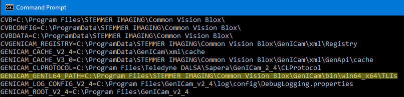
Transport Layer environment variable: GENICAM_GENTL64_PATH to find all *.cti files