|
|
Common Vision Blox 14.0
|
|
|
Common Vision Blox 14.0
|


What is the Image Manager?
Image Manager Components
Image Manager DLLs
Image Manager ActiveX Controls
CVB Technology
Common Image Model
The Image Object
Coordinate System, Origin and Areas
Multithreading
Supported File Formats
High Dynamic Range Images
Image file handling
Acquisition device drivers and CVB Programming Interfaces
How to use the virtual driver
How to deal with video files
Areas of interest
Density and transformation matrix
Image Data Access
Unicode Support
Web Streaming
Destructive Overlays - Overview
Non-destructive Overlays
GenICam and CV GenAPI
3D Functionality
ActiveX Controls
Example Applications
Visual C++ Examples
.Net Examples
The CVB Image Manager is the basis for every Common Vision Blox application. The unique functionality and approach of the CVB Image Manager as an open standard provides an excellent basis for custom algorithms and applications in industrial image processing.
The CVB Image Manager offers unrivalled functionality in image acquisition, image handling, image display and image processing. It contains an extensive set of basic functionality allowing you to control many different types of image acquisition devices, as well as a wide range of image handling and processing functions. Furthermore it provides an optimised display with DirectX support and non-destructive overlays, a flexible coordinate system and support for multithreaded operation.
Based on the CVB Image Manager feature for image data access, it is also easily possible to create special algorithms for your specific application, based on the tutorials delivered for all supported compilers.
The functionality of the CVB Image Manager can roughly be split into the following groups:
Image Acquisition
Image Display
Image Handling
Image Processing
All Image Manager components are to be found in %CVB%. The complete API is available as CVB Reference. The core technology is based on DLL library files containing the full functionality of the Image Manager:
| Image: CVCImg.dll | This core library contains functions to generate, manage and manipulate image objects |
| Driver: CVCDriver.dll | This library contains functions to control all image acquisition device drivers |
| GenICam API: CVGenApi.dll | This library contains functions, which provide easy control of a GenICam compliant device like a GigE Vision camera. |
| 3D: CVCore3D.dll | This 3D libraries contains the basic classes for manipulation of 3D data. |
| Utilities: CVCUtilities.dll | This library contains functions for accessing CVB image data directly as well as functions that are not directly associated with CVB e.g. High Performance counters |
| Display: CVCDisp.dll | This core library contains functions to control every aspect of displaying images (not documented - for internal use only) |
| File: CVCFile.dll | This undocumented library is used to read and write different file formats, it is based on the AccuSoft ImageGear library. |
| WebStreaming: CVWebStreaming.dll | This library contains functions to setup a server and stream images. |
To make handling easier five ActiveX components (OCX's) have been developed to contain the functionality of the core libraries:
CVImage Control , CVdisplay Control , CVGrabber Control , CVDigIO Control , CVRingBuffer Control , CVGenAPiGrid control , CV3DViewer Control.
All the ActiveX components have the same structure and follow the same design rules to reduce development times and increase flexibility. The most important property that each of the controls contain is the Image property which contains a handle to the image object referenced. At application runtime all controls need an image object for processing. This pipelining defines links between each CVB tool and image object. The following is an example of pipelining an image object from an Image control to a Display control:
CVDisplay.Image = CVImage.Image
It is not essential to use ActiveX components instead of DLL libraries but they can often be faster to develop with and easier to use. If a tool is available in ActiveX form then it has a number of standard methods and properties.
Each of the core Common Vision Blox DLLs (Dynamic Link Libraries) is described in more detail following the links.
| CVCImg.dll |
The CVCImg.dll library is the basis for all tool and application development. It contains facilities for:
Functions that address the Windows clipboard are also included. Find functionality with: Area, Matrix, Map, Rect, Coordinate, Dongle, License, Tool, Draw, Fill, Flood, Image, Create, Copy, Set, Write, Error, Object, etc. Image objects can be generated from both image files and driver files.
| CVCDisp.DLL |
The CVCDisp.dll library contains functions for displaying images under Windows:
Find functionality with: Display, Object, Overlay, Area, Label, Image, Window, etc. Images are displayed using standard Windows functions (DIB) or by means of DirectDraw, if DirectDraw is used all overlays are flicker-free.
| CVCDriver.DLL |
CVCDriver.dll is the one library that is continually growing within the Common Vision Blox concept. The library contains functions to
Find functionality with: BoardSelect and CameraSelect, DeviceControl, NodeMapHandle, Grab, Snap, Trigger, Image, Buffer, etc. A program or tool that requires a special interface should always verify if the required interface is available before attempting to access it.
| CVGenApi.DLL |
The GenAPI is part of the GenICam™ standard whereas the transport layer is typically provided by the camera or software vendor. The XML files are provided by the relevant vendor. At runtime, it may be necessary to modify individual camera features or present these to the end user. This can be achieved, on the one hand, using the CV Gen Api functions for accessing the CVB GenICam interface and, on the other, the Common Vision Gen Api Grid Control. The CVGeniApi.dll library contains functions to provide easy control of a GenICam compliant device like a GigE Vision camera.
Find functionality with: NodeMap, NM, Node, N, Load, Save, Get, Set, Info, etc.
| CVCUtilities.DLL |
This library contains
| CVCore3D.DLL, CVCore.DLL |
This libraries contain functions for
Find functionality with : Create, Transform, Calculate, Rotate, PointCloud, Matrix, Vector, etc.
Each of the ActiveX components is described in more detail below and following the links:
| Core library used to create the CV Image Control component: CVImage.ocx |
The CVImage Control is the basis for all tool and application development. It contains facilities for:
Functions that address the Windows clipboard are also included. Image objects can be generated from both image files and driver files.
| Core library used to create the CVdisplay Control component: CVDisplay.ocx |
CVdisplay Control contains functions for:
Images are displayed using standard Windows functions (DIB) or by means of DirectDraw, if DirectDraw is used all overlays are flicker-free.
ActiveX controls are available as simple wrappers for the CVCDriver.dll:
| CVGrabber Control: CVGrabber.ocx |
| CVDigIO Control: CVDigIO.ocx |
| CVRingBuffer Control: CVRingbuffer.ocx |
The CV GenAPI Grid Control contains functions to provides easy control of GenICam compliant devices like a GigE Vision cameras.
| Core library used to create the CV GenAPi Grid control: CVGenApiGrid.ocx |
The CV Core3D Viewer Control (3D Display Control) contains functions to handle 3D data.
| Core library used to create the CV Core 3D Viewer control: Display3D.ocx |
Common Vision Blox is an open platform for image processing and machine vision development.
To maintain an open platform it is important to communicate the underlying technology and concepts to all users and developers. Communicate this technology involves describing the
This document describes in detail the proposal for a Common Image Model, it is split into the following sections:
Linear memory representations
Virtual Pixel Access
VPA Compatible memory representations
Coordinate System
Example VPA Tables
Use also the Image data access chapter to get informations about working with CVB Images.
What constitutes an image?
Physically, images are created through optical projection of some section of the real world onto a two dimensional surface e.g. the retina, CCD or CMOS device. The incident light reacts with some discrete set of sensors (Rods, Cones, Photosites...) distributed over this surface, changing the state of each sensor which serves to record local properties such as gray value, color, etc.
To us, an image in its most primitive sense is a state of such an ensemble of sensors. Mathematically it is a function assigning to every sensor, a state in the sensor's state space.
Parametrizing the sensors by their surface coordinates and assuming that their states can be modeled in some common, finite dimensional vector space you arrive at an analytical model of images:
The set P, the dimension d and the function v are the essential properties of an image.
With a basis of V fixed, then equivalently to (2) and (3) there are scalar functions v0, v1, ..., vd - 1 such that v(X, Y) = (v0(X, Y), v1(X, Y), ..., vd - 1(X, Y)). The functions vi are essentially scalar (gray scale) images and are called color planes or more generally image planes (RedPlane, BluePlane, GreenPlane, HuePlane, IntensityPlane, SaturationPlane, ...). Again equivalently there is a scalar function v of [0, ..., d - 1] x P such that v(i, X, Y) = vi(X, Y) (e.g. v(Green, 100, 120) = 17.5, ...). This is the simplest and most general model of an image. It includes gray scale images, color images, pyramids, stereo images, finite time sequences of images,...
To make the model suitable for computing, three problems have to be solved:
a) The representation of the model in memory
b) Given (X, Y) rapid decision if (X, Y) is in P (a legal pixel)
c) The rapid computation and/or modification of the function v
Problems (a) and (b) are made solvable by the following simplifications
i. P is a sub-rectangle in a two-dimensional square lattice. In fact, since global translation of image coordinates is not relevant we can assume that (0, 0) is one of the corners of the rectangle.
Therefore P is specified by the integral image properties (Width, Height).
This allows problem (b) to be solved with four comparisons.
The lattice assumption causes problems in rotations and other geometric transformations, interpolation mechanisms have to be provided.
ii. The range of the functions vi is a set Ti of numbers conveniently handled by a computer. This ranges from 8-bit (usual) to 64-bit (double precision) scalars, and may perhaps vary from image plane to image plane.
The data type Ti should support basic arithmetic functions.
The number of bits to represent the i'th image plane is a further property of an image.
To summarise the definition of a CVB image here is a list of essential properties:
An image in the sense of CVB can therefore be regarded as a vertical stack of one-dimensional images. The height of the stack is the dimension of V (e.g. 1 for gray scale images, 3 for RGB color images, two for stereo or complex images, the height of the pyramid for pyramids, the length of the time sequence for time sequences, etc).
The diagram below illustrates the image concept.
The Coordinate system, defined by an origin and a 2x2 matrix,
Number of Image planes (Dimension)
Data type of up to 255 Bits per pixel per plane
Virtual Pixel Address Table (VPAT) per plane
The planes are double linked lists which can be manipulated.
Problem of representation of the image model in memory raises the question of compatibility. To make the software useful it has to be compatible with existing memory representations for restricted types of images, at least DIBs (because we work under Windows) and various image acquisition devices. If we disregard 1-bit and 4-bit DIBs we are still left with gray scale and color DIBs, which may or may not be upside down.
The situation is worse when we look at image acquisition device with conceivable combinations of interlaced, noninterlaced, 8-10-12-24-32 bit pixels, various schemes for color representations or possibly separate memory pages for the different color planes.
One solution is to fix some standard memory representation (e.g. DIB) and copy/translate an incoming image to this format whenever necessary. We reject this idea because it introduces redundant information involving additional memory and computation time (the argument that relative to processing, the copying time is negligible on modern systems is not acceptable, what if we just want to monitor the gray values of a few pixels?).
Instead, we propose to exploit the fact that most (flat) memory representations of image planes have a property of linearity: If the value for pixel location (X, Y) resides at address M(X, Y) then
M(X, Y) = M(0, 0) + X*DeltaX + Y*DeltaY
for some DeltaX, DeltaY. These, together with the base M(0, 0) can be regarded as properties of the image plane in question.
By communicating DeltaX and DeltaY together with M(0, 0) and some fundamental base offset for every image plane, we could augment the image model above with a description of how the pixels are placed in memory. This description would serve as a basis for a more rapid computation of the function v.
This is the starting point of the old MINOS driver model. Essentially the driver model replaced the idea of »image data« with »knowledge about image data«.
Rather than communicating the data itself, the driver only communicated information about the organization and location of the data.
The linearity formula above has three disadvantages:
The current version of Common Vision Blox resolves these three problems internally. By publishing the underlying mechanism, and simplifying and streamlining the definitions, the method can be made the basis of an image description format that is suitable for the purposes of high-speed machine vision.
The greatest problem in image processing is the rapid computation and/or modification of the function v. Given a linear memory representation of an image plane this amounts to rapid computation of the address
M(X, Y) = M(0, 0) + X*DeltaX + Y*DeltaY
for a given image plane. This is done in CVB with the aid of tables to effect the two multiplications involved and simultaneously resolve complexities such as interlaced scan lines.
To understand the basic idea we introduce two functions (tables)
XTable ( X ) := M(0, 0) + X*DeltaX, for X = 0, ..., Width - 1 and
YTable ( Y ) := Y*DeltaY, for X = 0, ..., Height - 1.
Then the address is computed by
M(X, Y) = XTable ( X ) + YTable ( Y ),
which can be computed very rapidly.
The pixel reference tables XTable and YTable provide random access to pixels in a few clock cycles. Details and the associated data structures are described in the next section which also explains how the tables are to be programmed.
In addition to providing random access, the tables are able to influence the underlying image geometry without any loss in subsequent computation time:
Suppose you interchange the tables, the resulting image is reflected and rotated by 90°. If you also reverse the order of one of the tables the result is a rotation without reflection. By omitting (duplicating) every other value in both tables you shrink (enlarge) the image by a factor of two. Practical applications are the zoom function in image display and the squaring of pixels from non square pixel image acquisition device.
It is important to realise that these operations need computations in the order O(Width + Height) when programmed through the tables while the order is o(Width * Height) if the computations are carried out on the images themselves.
This is typically larger by a factor > 100. Of course the tables have to be programmed just once for a given target geometry of an image plane.
We propose the tables as descriptors for images. We know of no other addressing scheme possessing the same generality, speed and flexibility. The principal philosophy is to shift the attention from the specific memory layout of an image to information about this layout.
It seems appropriate to call the corresponding image addressing virtual pixel access, VPA in short.
The VPA scheme clearly resolves the problem of interlaced images (an example is included). It would, in fact, also describe an interlaced image, where the odd field is upside down and the even field rightside up or more pathological cases.
It is interesting to identify the class of memory representations which can be represented by VPA tables.
The class evidently includes all linear representations. Which are excluded? The equation
M(X, Y) = XTable ( X ) + YTable ( Y ),
evidently implies that
M(X1, Y) - M(X2, Y) = XTable ( X1) - XTable(X2) is independent of Y, so that
M(X1, Y1) - M(X2, Y1) = M(X1, Y2) - M(X2, Y2)
for all X1, X2, Y1, Y2 which is equivalent to
M(X1, Y1) + M(X2, Y2) = M(X1, Y2) + M(X2, Y1),
for all X1, X2, Y1, Y2.
This equation exactly describes image planes which can be described by VPA tables. It must hold if the tables exist. On the other hand if the formula is valid then the required tables are easily seen to be
XTable(X) = M(X, 0) - M(0, 0)
YTable(Y) = M(0, Y)
The asymmetry is only superficial. We could have subtracted M(0,0) from the Ytable entries just as well.
In more intuitive terms the basic condition is that in memory, all scan lines (chaotic as they may be) are translations of each other, and that (equivalently) all scan columns are also translations of each other. Excluded memory representations therefore change the representation scheme between scan lines.
An example of an excluded representation is a four-quadrant type of frame grabber where the quadrants are mapped to essentially random offsets in memory. If the quadrants are mapped to equidistant offsets in memory (e.g. sequentially) the representation is already covered by VPA (bizarre as it may be).
This discussion is somewhat academic. We may simply summarize: Almost all practically relevant memory formats can be represented by VPA.
Examples for the most common ones will follow.
Normally the coordinate system of an image is fixed by the image itself. The origin is at the top left corner. The x axis extends along the top of the image, and the y axis extends down the left side. The unit of measure is one pixel.
In many applications a flexible coordinate system can be a helpful tool. The coordinate system in CVB consists of the origin and a matrix defining the linear transformation of the image. A linear transformation can be described by a matrix A where:
The matrix A acts on any vector according to the equation:
A<x, y> = <x', y'> = <x*a11 + y*a12, x*a21 + y*a22>
Since each pixel in an image can be considered as a vector <x, y>, the matrix A acts on each pixel according to equation I, thus accomplishing linear transformation.
For example, the matrix A defined below acts on an image by doubling its height and doubling its width (a scaling factor of two).
So, any pixel <x,y> in the image is transformed into the pixel <x', y'> where, by equation I:
<x', y'> = <x*2 + y*0, x*0 + y*2> = <2x, 2y>
Consider the pixel <50, 80>: A<50, 80> = <2*50, 2*80>
The unit of measure becomes 1/2 pixel rather than one, thus increasing the virtual size of the image to 200% of its actual size.
There is no need for an application to support the coordinate system but it is often nice to have such a tool. This calculates the position of a point P (without CS) to a position in the image CS system:
P' = P * CS + Origin
To refute the possible objection that the tables, although convenient and fast to use, are somewhat complicated and difficult to create we will present a small number of practical examples.
First we state the equations defining the tables for a generic linear memory representation, then specialise with some frequent cases and also present examples outside the scope of linear representations.
Generic linear memory representation:
M(X, Y) = M(0, 0) + X*DeltaX + Y*DeltaY
VPAT [X].XEntry := M(0, 0) + X*DeltaX
VPAT [Y].YEntry := Y*DeltaY
The equations for the tables are always understood for X = 0, ..., Width - 1 and Y = 0, ..., Height - 1.
Note that the tables can be programmed sequentially so that multiplications do not have to be carried out. It suffices to add DeltaX or DeltaY when incrementing the table index. The same simplification applies to most other equations below, however even if multiplication were carried out it the overhead would not be high: The tables have order o(Width + Height) as opposed to the image itself which has order o(Width * Height). It is also important to remember that they need to be programmed just once for an image object.
Note that the way the VPA tables are used, we could have included offset M(0, 0) just as well in the Ytable as in the Xtable.
Example 1
For a practical example first consider an 8-bit gray scale image with width W and height H, the gray values are sequentially written in memory, with the address incremented from the last pixel of one scan line to the first pixel of the next scan line. A simple 4-byte pointer lpImage points to the first pixel in the first scan line (this is the simplest image format):
IImage.Dimension = 1
IImage.Width = W
IImage.Height = H
IImage.Datatype = 8
(We omit the index for one-dimensional images)
IImageVPA.BaseAddress = lpImage
IImageVPA.VPAT [X].XEntry = X
IImageVPA.VPAT [Y].YEntry = Y * W
Example 2
Next in complexity we consider an 8-bit DIB in the upside down format where the last scan line comes first in memory. There is an added complexity because, for DIBs, the scan lines wrap on Dword boundaries. In this case we have the pixel data represented by a memory handle hImage which needs to be locked in memory prior to addressing:
IImage.Dimension = 1
IImage.Width = W
IImage.Height = H
IImage.Datatype = 8
IImageVPA.BaseAddressIndex) = lpImage
IImageVPA.VPAT [X].XEntry = X
IImageVPA.VPAT [Y].YEntry = ((W + 3) and 0xFFFFFFFC)*(H - Y - 1)
The complicated »(W + 3) and 0xFFFFFFFC)« simply gives the length of a scan line in memory extended to Dword boundaries.
The factor (H - Y - 1) implements the upside down order of scan lines: For Y = 0 this is (H - 1) i.e. the last scan line in memory and the first in the logical image. For Y = H - 1 (last row in image) it becomes zero, addressing the first scan line in memory.
Example 3
Here is the image definition for a 24-bit RGB DIB, again upside down, referenced with a simple pointer lpImage to the bitmap data.
Recall that the values in memory are now BGRBGRBGR..., however we want plane 0 to refer to the red plane (otherwise it would be a BGR image):
IImage.Dimension = 3
IImage.Width = W
IImage.Height = H
IImage.Datatype = 8
(Don't let this confuse you: the 24 bits refer to RGB, individual color planes are still 8-bit images)
IImageVPA.BaseAddress = lpImage
IImageVPA.VPAT[X].XEntry = 3*X
IImageVPA.VPAT(0)[Y].YEntry = ((3*W + 3)and 0xFFFFFFFC)*(H - Y - 1) + 2 (The added »2« takes care of the red plane)
IImageVPA.VPAT(1)[Y].YEntry = ((3*W + 3)and 0xFFFFFFFC)*(H - Y - 1) + 1 (Green plane
IImageVPA.VPAT(2)[Y].YEntry = ((3*W + 3)and 0xFFFFFFFC)*(H - Y - 1) + 0 (Blue plane)
Note that the Xtable does not depend on the color.
Example 4
Now you may want to regard the RGB image as a single entity rather than as a stack of three gray images. In this case you can change the definition to the following (listing only the functions which change):
IImage.Dimension = 1
IImage.Datatype = 24 (This provides the desired 24-bit BGR pixels)
IImageVPA.VPAT[X].XEntry = 3*X
IImageVPA.VPAT[Y].YEntry = ((3*W + 3) and 0xFFFFFFFC) * (H - Y - 1)(Addressing the BGR scan lines)
Example 5
A single, elegant formulation combines both cases by creating a four-dimensional image where planes 0, 1 and 2 give the R, G and B images, respectively, and plane 3 the combined BGR pixels:
IImage.Dimension = 4
IImage.Width = W
IImage.Height = H
IImage.Datatype(Index) = 8 for Index = 0,1,2 and
IImage.Datatype (3) = 24 (Here the fourth plane actually has a different data type)
IImageVPA.VPAT[X].XEntry = 3*X
IImageVPA.VPAT(0)[Y].YEntry = ((3*W + 3) and 0xFFFFFFFC) * (H - Y - 1) + 2 (The added »2« takes care of the red plane
IImageVPA.VPAT(1)[Y].YEntry = ((3*W + 3) and 0xFFFFFFFC) * (H - Y - 1) + 1 (Green plane)
IImageVPA.VPAT(2)[Y].YEntry = ((3*W + 3) and 0xFFFFFFFC) * (H - Y - 1) + 0 (Blue plane)
IImageVPA.VPAT(3) = IImageVPA.VPAT (2)
Addressing for the fourth plane is the same as for the blue plane. Only interpretation of the address content is different.
Example 6
Next we consider a complex, double-precision image such as the output of some FFT functions. One memory block (lpReal) contains the real values, the other (lpImaginary) the imaginary ones in a simple scan line format (as the first example). We want to interpret plane 0 as the real part and plane 1 as the imaginary part:
IImage.Dimension = 2
IImage.IWidth = W
IImage.IHeight = H
IImage.Datatype = 64 + float + signed (Each plane has double-precision pixel values)
IImageVPA.BaseAddress (0) = lpReal
IImageVPA.BaseAddress (1) = lpImaginary
IImageVPA.VPAT [X].XEntry = X*8
IImageVPA.VPAT [Y].YEntry = Y*W*8
Note that in this case a pointer to one VPA table can be used for both image planes.
Example 7
In the next example a frame grabber (512 x 512 x 8) has non-square pixels with an aspect ratio of 3:2 and deposits the scan lines in interlaced format, the even field in the first 128 K of the memory block and the odd field in the second one. Part of the object is to square the pixels by mapping linearly onto a 768 x 512 rectangle (without anti-aliasing).
IDimension = 1
IWidth = 768
IHeight = 512
IDMType (Index) = 0
IDMBaseAddress (Index) = lpImage
VPAT [X].XEntry = (2*X) div 3
This performs the squaring of pixels
VPAT [Y].YEntry = 512*(Y div 2) for even Y and
VPAT [Y].YEntry = 131072 + 512*(Y div 2) for odd Y
Subsequent to programming of the tables, the complexities of the interlaced case are hidden to any processing software.
Also this is a situation where the geometry of an image is actually modified using the tables - virtually squaring the pixels. Of course the resulting image still has a fault resulting from aliasing (in every row every other pixel is duplicated).
Nevertheless, if an algorithm is not too sensitive to high local frequencies it can be ported to this type of image without modification.
Note that in all of the above examples, the image pixels are accessed in a unified way once the tables have been programmed. If we forget about the complex floating point and BGR images for the moment, we can actually state that any processing routine which works on one image plane of the above images will also work on all the other image planes of all the other images above.
Example 8
In the next example we suppose an image A as already been defined in the VPA syntax above, and describe the definition of another image B, of prescribed width wb and height hb, mapping a subrectangle [Left, Top, Right, Bottom] of image A onto [0, 0, wb - 1, hb - 1].
IDimensionB = IDimensionA
IWidthB = wb
IheightB = hb
IDMTypeB (Index) = IDMTypeA (Index)
IDMBaseAddress (Index)= IDMBaseAddressA (Index)
This implies that the memory for image A must not be freed while image B is in use. See reference counting below.
VPATB [X].XEntry := VPATA [Left + (X * (Right - Left)) /(wb - 1)].XEntry
VPATB [Y].YEntry := VPATA [Top + (Y * (Bottom - Top)) /(hb - 1)].YEntry
The tables implement the affine map required (this method of scaling again does not provide any antialiasing). In a similar way, images can be virtually rotated by 90° or reflected - always with a number of computations in the order of o(Width + Height) rather than o(Width * Height).
Finally we describe a problem which occurs when filtering an image with a convolution kernel, and its solution using VPA. In this case the output is first defined for possible translation positions of the kernel within the input image. Assuming a 5 x 5 kernel and a 512 x 512 input image, the output image would be 508 x 508. This is implemented in the present version of MINOS, resulting in harsh criticism by users who wish the output image to have the same dimensions regardless of the arbitrary definition of the boundary pixels.
The additional pixels cannot be left completely uninitialized. It has been proposed to copy the values of adjacent, well defined pixels to the fringe pixels after the filtering. Our suggestion is to extend the input image at the fringes before filtering to create a 516 x 516 image which is then filtered in a straightforward way.
Extending the image is very simple with the tables. Suppose we want to extend the image by DFringe on each of the four sides. This is done by
VPAT [X].XEntry := VPAT [0].XEntry - DFringe <= X <0 ,
VPAT [X].XEntry := VPAT [Width - 1] .XEntry for Width - 1<X<= Width + DFringe - 1,
VPAT [Y].YEntry := VPAT [0].YEntry, for -DFringe <= Y <0 ,
VPAT [Y].YEntry := VPAT [Height - 1].YEntry for Height - 1<Y<= Height + DFringe - 1.
This requires an overhead of 4*DFringe operations when the tables are programmed and saves 2*DFringe*Width + 2*DFringe*Height operations when the image is filtered.
The additional memory requirement is 16*Dboundary bytes. If we regard, say 9 x 9, as the largest kernel size we wish to implement without any special processing, this additional memory requirement is 64 bytes which is so small that we propose to make such an extension the standard for images.
It is important to understand that the Image Object is considerably more than simply image data. It should be considered as a
The images have width, height and the third dimension is depth, this third dimension can be used for colour images, stereo images, image sequences and many other image processing techniques. The data type for each plane can be set separately and can contain data with up to 250 bits per plane, signed, unsigned, fixed or floating point.
This section contains very detailed information about the Image Object. It is important to understand that the Common Vision Blox concept allows users full control over very powerful objects without the need for this detailed information, this information is provided primarily for tool developers who require more in-depth knowledge.
Image data can be accessed via a base address and a pixel offset, this offset information is stored in a virtual pixel access table (VPAT) which contains the offsets for a line, y, and for a pixel, x.
Every plane in an image object contains a separate VPAT and base address. Using this powerful approach to data access, zoomed, expanded, rotated and geometrically shifted images can be created very quickly without the need to copy or manipulate data but by simply rewriting the VPAT. In addition, the base library provides some optimised functions for accessing image data, these can be used by users who do not need background information on the structure of the image object. The Image Object is a Microsoft compatible COM object (For further information on COM objects can be found in ”Inside OLE Second Edition” written by Kraig Brockschmidt and published by Microsoft Press).
The important aspect of the Image Object is that it is NOT a Microsoft COM object but a Microsoft COMPATIBLE COM Object, this means that no Microsoft header files or libraries and no Microsoft compilers are needed to generate an image object. The only condition is that the compiler must be able to process object-oriented code.
The COM standard allows an object to be accessed via interfaces. Once defined, interface functions are not allowed to be changed, however new interfaces permitting access to the actual object data are allowed to be created. The Common Vision Blox Image Object has implemented a number of interfaces including the IImageVPA interface.
Images which have been acquired by an image acquisition device like a frame grabber are a special case within this concept, an image acquisition device driver has other interfaces in addition to the IImageVPA interface. As an absolute minimum for a driver, the IGrabber interface must have been implemented. This interface provides the Grab, Snap and ShowDialog functions with which images can be acquired from a camera, they are the absolute minimum for the device functionality. Other interfaces can be attached to the image object to support special hardware features such as display, trigger or digital I/O. The image object itself is the handle for the IImageVPA-Interface, this handle can be used to query whether other interfaces have been implemented and are available. The result of the query is a handle for the queried interface, this handle can be used to access all the functions in that interface. Providing an image is not reassigned and therefore the handle defines a different image object, the query for the interfaces only has to be performed once when the application starts.
One element of the Image Object is the coordinate system, image data is accessed through the coordinate system and it consists of the origin and a 2 x 2 transformation matrix. Linear transformations can be implemented using the matrix which effects all the image data accessed through the coordinate system. The coordinate system can be used for many different functions, for example, a frame grabber delivers an image with non-square pixels, the aspect ratio can be corrected by means of the transformation matrix.
NOTE: Not every tool supports the coordinate system (CS), for example CVB Minos, CVB Edge support the CS but CVB Barcode and CVB Manto do not. As a general rule if a tool requires a region of interest in Area Mode (X0, Y0, X1, Y1, X2, Y2) then is does support the CS, if the region of interest is required in Rectangle Mode (Top, Left, Bottom, Right) then is does not support the CS.
These examples offer 2 ways in which the driver interface can be used, there are many many possible options, these are offered as examples to stimulate the user's imagination to consider other uses.
This driver model differs from many other driver models in commercially available software, the two main aspects are : 1.No image data is exchanged between the driver layer and user layer, only information about the position and orientation of the image data. This has a considerable increase in speed compared with interfaces based on ReadLine or ReadRect concepts that copy data internally.
2.The interface can be extended dynamically without giving rise to compatibility problems. Existing interfaces are not allowed to be changed and if an application uses an interface named MyInterface and other interfaces are added to the driver (possibly years later), then the application can still work with the driver because MyInterface has not been changed and its address is ascertained at program runtime.
Please see the section 'Proposal for a Common Image Model' for more detailed information on the components of the Image Object.
This section discusses two of the most powerful features of Common Vision Blox: the coordinate system and the selection of subareas of an image (defined by P0, P1, and P2).
Normally the coordinate system of an image is fixed by the image itself. The origin is at the top left corner. The x axis extends along the top of the image, and the y axis extends down the left side. The unit of measure is one pixel. Points, rotations, subimages and the sizes of features in an image are all defined with respect to the image coordinate system.
The coordinate system is implicit in the image, it overlays the image and is established according to your instructions. You specify the origin, determine the orientation and define the unit of measure. Thus, you control the structure on which positions, rotations and areas are based.
Dynamically within Common Vision Blox you can specify the virtual origin within an image to which all other points relate, it is also possible to do any or all of the following :
When you specify an area of interest (AOI) in a SubImage, Histogram or other task which uses the area structure, the area is fixed with respect to the coordinate system in effect at the time the task executes. This means that the AOI is translated, rotated or scaled according to changes made dynamically in the coordinate system. Because of this capability and the fact that you can define the CS with respect to a defined position, you can :
Note: The rest of this section discusses these features in more detail. Refer to chapter Areas for further information on defining subareas, their orientation and controlling the search direction within them.
In many applications a flexible coordinate system can be a helpful tool. The coordinate system in Common Vision Blox consists of the origin and a matrix defining the linear transformation of the image. A linear transformation can be described by a matrix A where:
The matrix A acts on any vector according to the equation:
A<x, y> = <x', y'> = <x*a11 + y*a12, x*a21 + y*a22>
Since each pixel in an image can be considered as a vector <x, y>, the matrix A acts on each pixel according to equation I, thus accomplishing linear transformation.
For example, the matrix A defined below acts on an image by doubling its height and doubling its width (a scaling factor of two).
So any pixel <x, y> in the image is transformed into the pixel <x', y'> where, by equation I:
<x', y'> = <x*2 + y*0, x*0 + y*2> = <2x, 2y>
Consider the pixel <50, 80>: A<50, 80> = <2*50, 2*80>. The unit of measure becomes 1/2 pixel rather than 1, thus increasing the virtual size of the image to 200% of its actual size.
It is not essential for an application to support the coordinate system but it is often a very useful tool. This calculates the position of a point P (without CS) to a position in the image CS system: P' = P * CS + Origin
The coordinate system provides a reference system for the description of areas. Using CVB DLLs you can reset the origin and the CS vector dynamically.
When the first BMP image is loaded, the CS origin is at the top left corner (x = 0, y = 0). The coordinate system vector (CS vector) that describes the scale and rotation of the coordinate system is <1, 0, 0, 1> (given in pixel coordinates). Its equivalent polar form is polar (1,0) in which the modulus (first coordinate) indicates that the image is at a 1:1 scale, and the argument (second coordinate) indicates that the coordinate system is rotated an angle of 0° from the top border of the image.
The flexibility of the CVB coordinate system allows you to move an image into the »right« place (translation), give it the »right« orientation (rotation), and change it to the »right« size (scaling) while you are looking at it.
The CS origin defines the translation by specifying the pixel coordinates of the coordinate systems origin, relative to the top left corner of the image (y-axis increases downward).
The CS vector describes the combined effects of rotation and scaling. Its modulus is the scaling factor and its argument is the angle of rotation.
The vectors are defined as follows:
P0 The origin point of the parallelogram. The task is performed in relation to it
P1 The corner that defines the direction of scan lines in the parallelogram
P2 The corner that defines the search direction in the parallelogram
P0', P1', and P2' are the standard vector variables CurrentP0, CurrentP1, and CurrentP2, and are calculated according to the following equation:
Pn' = Pn * CS + Origin
where CS is the current CS vector and Origin is the current CS origin.
P0, P1, and P2 are defined in relation to the current CS and remain fixed with respect to it. So, as the CS is translated, rotated, or sized so is the subarea. P0', P1', and P2' are defined in relation to the current image, therefore they change according to changes in the CS.
Through definitions of P0, P1, and P2, you control the orientation of the subimage as well as its size, shape and location.
So for example you can 'Cut Out' a subimage whose sides are not parallel to the sides of the image. When the subimage becomes the current image, P0 is the origin, P1 defines the x axis, and P2 defines the y axis.
If you want to keep a subarea you have selected, but want it rotated (by 90°, for example) when it is passed into the data frame, simply change the settings of P0, P1, and P2 so that they specify different corners of the same rectangle. (Compare this illustration to the previous one.)
In Scan tasks (ScanPlaneUnary, ScanPlaneBinary, ScanImageUnary and ScanImageBinary), these vectors also determine the scan direction and search direction.
So, by controlling the vectors you can change the scan direction. The first scan line is always from P0 to P1, and the scan direction is always from P0 to P2.
Related Topics
Image Control - Property Pages
Image Dll - Coordinate System Functions
The following section describes the use of multithreading in Common Vision Blox.
These notes are targeted primarily at users who have multiple image acquisition devices in a system, or who are working with the Coreco Imaging IC-Async. Registry settings are described and should only be used in the above cases. It is highly advisable not to make any changes to registry settings if only one frame grabber or no IC-Async is installed in the system.
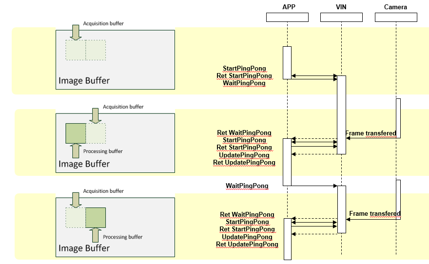
We will be looking at the ping-pong method of acquisition in a separate thread. It appears somewhat complicated on the surface and there are also two different methods, the difference is only slight but difficult to describe. Readers who have already developed multithreading applications will recognize the difference easily. The following figure shows the non-default method:
This case only applies when the driver that is used supports ping-pong and the PingPongEnabled property of the Image Control has been set to TRUE. When the Grab property is set to TRUE for the first time, a separate thread is started. This thread runs in parallel to the application thread and serves exclusively to acquire images with the aid of the ping-pong interface. However, the images generally need to be processed in the application and the two threads must therefore be synchronized in some way. This synchronization is done by means of events.
An event is a connection between occurrences in the Control and the application in which the Control is located. The end points of this connection are called the event source and event sink. When the event has been triggered, the Control branches to this function if a sink function has been specified in the application. Basically, an event can therefore be regarded as a callback function.
Now we come to the difference between the two methods : In the first method the ImageSnaped event is executed directly from the acquisition thread of the Control , and is not passed to the applications message queue for further processing. For the application, this means that everything that is done in the event potentially involves unreliable thread handling. A classic example of this is a list of threads which is processed in the ImageSnaped event. At the same time the program provides buttons with which new threads can be inserted in the list or existing ones deleted from it. If no synchronization takes place, users can delete a thread from the list while this element is being accessed in the event. Inexperienced users fall into an unpleasant trap if they are not aware of this situation. For this reason we have implemented a simple form of synchronization with the user interface in the Common Vision Display and Image Controls.
The event is triggered by the client's message queue. This ensures that no user inputs are possible while the event is executing. This is the second, non-default method.
Switching between the two modes is implemented by a flag in the registry. Under HKEY_LOCAL_MACHINE\SOFTWARE\Common Vision Blox\Image Manager there is a DWORD value named GlobalAsyncACQ Enabled. A value other than 0 disables synchronization via the message queue. A value of 0 (default) enables it. The default value should not be changed for normal applications. If, however, multiple image acquisition device instances and thus multiple Image Controls are in use, the value should be changed to ensure that the application handles threads reliably.
A simple test illustrates the difference. Take two Image Controls and load two drivers. Each Control is assigned a driver instance. A Sleep(1000) is called in the ImageSnaped event of one Control . If the Grab property of both Controls is set to TRUE, the second display acquires new images at frame rate whereas the first display only acquires a new image every second. This requires Global AsyncACQ Enabled to have been set to 1, the two displays therefore run in parallel.
If Global AsyncACQ Enabled has been set to 0, the two displays run at just one image per second because the slower thread delays the other one (there is only one message queue).
Experienced developers will have noticed a striking infringement of the Microsoft Windows Design Rules in the case of asynchronous acquisition. According to Microsoft, the user interface (UI) is not allowed to be accessed from multiple threads at the same time. This is understandable because the output device only has one logical pixel x, y which can only assume one state. Some kind of synchronization between the threads is therefore needed.
This puts Common Vision Blox in a tricky situation because users can extend the acquisition thread by means of the ImageSnaped event. For instance, users can call the AddDisplayLabel method, which draws a label over the image as an overlay, in the ImageSnaped event. In this case, changes are made to the UI from the thread. Common Vision Blox could provide safeguards against all dangerous calls but this would lead to a drop in performance, therefore the Image and Display Controls open up their internal synchronization objects allowing users the opportunity to ensure that their calls handle threads reliably. Everything that is under the direct control of Common Vision Blox (e.g. interactive zooming, scroll bars etc.) is safeguarded internally.
All external UI functionality has the potential for unreliable thread handling, it has to be made reliable by means of synchronization objects. At this point we must stress that this tricky situation does not originate solely with Common Vision Blox UI calls but affects all outputs with Windows UI functions in all programs. If, for example, MFC is used to display text in a text box from a second thread, the program will crash pitilessly. Visual C++ users, however, must draw upon SDK functions to enable UI outputs from a separate thread.
Two methods are available in the Controls for synchronization:
Lock () : ... locks all internal outputs of all instances of the Image or Display Control
Unlock () : ... unlocks the above
If labels are to be added to an image in the ImageSnaped event, the CVDisplay.AddLabel(...) call has to be inserted in a Lock-Unlock block. Of course, there is only necessary if GlobalAsyncACQ Enabled has been set to a value other than zero which, in turn, only makes sense if multiple independent acquisition threads have to run (e.g. when multiple image acquisition devices are going to be used simultaneously).
The acquisition thread thus branches to the application using one of the two methods described above and remains there until the event function is exited. The reason for this is that we want to evaluate images. There is no point running a thread that constantly acquires new images which cannot be processed, thereby consuming valuable computation time. In the figure above, the course of the acquisition thread is marked in red.
Attentive readers will have noticed a disadvantage of the implementation here. The application is not told in any way whether all images were processed or how many images were not processed. The application may need to acquire various images quickly one after another for processing later. The solution to this lies not just in creating a memory area for the image but also in managing the images in a circular buffer of adjustable size. If the circular buffer is big enough, the application described above can be implemented. Such a procedure can be implemented with the functions that are currently available in Common Vision Blox (see Sequence tool for example).
Related Topics
GetGlobalAsyncACQEnabled and SetGlobalAsyncACQEnabled functions from Utiilites Dll
Lock and Unlock method of the Display Control
Common Vision Blox supports a number of standard and non-standard file formats. Non-standard file formats are often required to store extended information, for instance Windows graphics file formats do not offer the ability to store Common Vision Blox coordinate system information, for this reason a proprietary CVB format exists.
The hardware independent architecture of CVB requires a Video INterface file (VIN) to be loaded when an image acquisition device like a frame grabber or camera is used, the VIN format is proprietary to CVB and supports a wide variety of interfaces for ping pong acquisition, linescan acquisition, triggered acquisition and many more.
Video files such as AVI or MPG can be handled as an image acquisition device, meaning they expose at least the IGrabber interface which is used to acquire frame by frame of the video file. This functionality is also available for a list of images that is defined in the so called EMUlator file format. A list of any graphic files can be defined in a simple text file (extension *.EMU). Once the EMU file is loaded as an image it exposes the IGrabber interface.
Graphics File Formats
Video files
VIN Format ( image acquisition devices)
MIO Format
EMU Format
Common Vision Blox supports several standard and non-standard image file formats and it does so using different libraries for loading and saving different image formats. Find below a list of the supported formats along with some additional information :
The Windows Bitmap format is perhaps the most important format on the PC platform. CVB supports BMP files with either 8 bits/Pixel (monochrome) or 24 bits/Pixel (colour). RLE-compressed BMP can neither be loaded nor saved with CVB. BMP file format support for CVB is native to the CVCImg.dll, i. e. no additional libraries are used for that format.
The MIO file format (MIO = Minos Image Object) is an uncompressed format proprietary to CVB and may only be loaded and saved using CVB-based software (e. g. the VCSizeableDisplay.exe sample application).
The MIO format supports any kind of image representation that CVB supports, i.e. you may have an arbitrary number of planes per image, any bit-depth supported by CVB, even floating point pixels. Additionally the MIO format contains the coordinate system associated with the image object, plus the overlay information of your image (if the image has been created as an overlay image). MIO support is again native to the CVCImg.dll.
The TIFF-format is a very widespread format on several computer platforms. However, the TIFF standard itself is quite complex and offers a huge variety of pixel formats, additional tags, planes etc. Therefore almost all software packages support only a certain subset of the official TIFF standard - and CVB is no exception to this. TIFF formats supported by CVB are from 8 to 16 bits/Pixel for one (monochrome) or 3 channels (colour). Reading is supported for uncompressed images, LZW77 compressed images and Packbits compressed images. Huffman-coding and Fax-coding are not supported as they would result in images with less than 8 bpp. TIFF support in CVB is achieved through the libtiff library, version 3.5.7, Copyright (c) 1988-1997 Sam Leffler, Copyright (c) 1991-1997 Silicon Graphics, Inc.
The source of libtiff is available from www.libtiff.org. For the complete libtiff copyright notice see below.
The JPEG format is the perhaps most popular and most widespread image format with lossy compression. JPEG support in CVB comprises 8 bpp images (monochrome) and 24 bpp images (colour) with jpeg compression. There is an inherent limitation to images of 65536 pixels width and height in jpeg formats. To adjust the compression level use the functions SaveLossyImage (method of the image Control ) or WriteLossyImageFile (function from the CVCImg.dll).
Valid quality values range from 0.1 to 1.0). The default compression factor is 0.7. JPEG support in CVB is fully based on the libjpg library version 6 provided by the Independent Jpeg Group, Copyright (C) 1991-1998, Thomas G. Lane, www.ijg.org. JPEG2000 (*.j2k, *.jp2, *.jp2k, *.jpc, *.jpx) The comparatively young JPEG2000 format is - much like its ancestor JPEG - a lossy image compression format based on wavelet compression technology. It is recommended to use this image format only on fairly up-to-date computers, because JPEG2000 compression and decompression are extremely time consuming. The boon of using JPEG2000 is a comparatively good image quality even at higher compression ratios (like JPEG, JPEG 2000 supports a quality parameter that may be set using the functions SaveLossyImage (method of the image Control ) or WriteLossyImageFile (function from the CVCImg.dll).
Valid quality values range from 0.002 to 1.0. The default compression factor is 0.075. Under CVB, JPEG2000 supports image formats with 8, 10, 12 or 16 bpp (monochrome) as well as 3x8, 3x10, 3x12, 3x16 bpp (colour). JPEG2000 support in CVB is based on the free j2000 codec available from https://jpeg.org/jpeg2000/. The following file formats are supported in CVB through the commercially available AccuSoft ImageGear library. They are available in CVB for the sake of completeness and flexibility, however we strongly recommend that you use the image formats listed above that cover most of the possible applications and offer a reasonably wide range of portability. All of the formats below support 8 bpp and 24 bpp images only, the only exception being WMF which only supports 24 bpp. For IFF and TGA both the RLE-compressed and the uncompressed variant are supported. Please note that the GIF support has been removed.
For more information and examples see chapter More Basics - Image file handling (load and save).
The Minos Image Object (MIO) file format is proprietary to CVB. This format saves the image data as well as the coordinate system and origin information. This extended information could be used to store calibrated spatial information, coordinate information used for correlation or simply information about a processed image.
The MIO format allows to store images with more than 8 Bit image data called High Dynamic range images (HDR).
This CVB AVI driver enables access to DirectShow compatible video files via the grabber interface of Common Vision Blox. Among the supported file types are AVI and MPEG formats, but effectively the selection of compatible file formats depends on the codecs installed on your system. As a general rule of thumb, most video formats that can be replayed using Microsoft Media Player can also be used with this driver.
For more details regarding the AVI driver take a look extra chapter How to deal with Video files.
The Video INterface (VIN) files are used in Common Vision Blox to access different frame grabbers, cameras and other real or virtual devices. The are at their core DLLs that contain the adaption of the hardware abstraction layer of Common Vision Blox for a given data source and are commonly referred to as "drivers" or "vin drivers" in Common Vision Blox. For details refer chapter Image acquisition device drivers.
An EMU file is a simple text file defining a number of images to be loaded. Using the IGrabber interface the application can 'acquire' from the image list. Of course all images must have the same size and the same number of planes. For details refer extra chapter How to use the virtual driver (EMUlator).
libtiff Copyright notice:
Copyright (c) 1988-1997 Sam Leffler Copyright (c) 1991-1997 Silicon Graphics, Inc. Permission to use, copy, modify, distribute, and sell this software and its documentation for any purpose is hereby granted without fee, provided that (i) the above copyright notices and this permission notice appear in all copies of the software and related documentation, and (ii) the names of Sam Leffler and Silicon Graphics may not be used in any advertising or publicity relating to the software without the specific, prior written permission of Sam Leffler and Silicon Graphics. THE SOFTWARE IS PROVIDED "AS-IS" AND WITHOUT WARRANTY OF ANY KIND, EXPRESS, IMPLIED OR OTHERWISE, INCLUDING WITHOUT LIMITATION, ANY WARRANTY OF MERCHANTABILITY OR FITNESS FOR A PARTICULAR PURPOSE. IN NO EVENT SHALL SAM LEFFLER OR SILICON GRAPHICS BE LIABLE FOR ANY SPECIAL, INCIDENTAL, INDIRECT OR CONSEQUENTIAL DAMAGES OF ANY KIND, OR ANY DAMAGES WHATSOEVER RESULTING FROM LOSS OF USE, DATA OR PROFITS, WHETHER OR NOT ADVISED OF THE POSSIBILITY OF DAMAGE, AND ON ANY THEORY OF LIABILITY, ARISING OUT OF OR IN CONNECTION WITH THE USE OR PERFORMANCE OF THIS SOFTWARE.
In general, Common Vision Blox provides possibilities to handle high dynamic range images with more than 8 bit per pixel image data. Here is a short overview of the possibilities, some hints and restrictions.
Acquiring HDR images
CVB is able to work with combinations of frame grabbers and cameras which provide images of 10 , 12 or 16 bit pixel data type.
Display of HDR images
In all cases, where a high dynamic range images is assigned to a CV Display control the output will lead to undesired results for colors greater than 255 (white in 8bit). This is due to the fact that only the least 8 significant bits in gray values will be displayed, the other pixel channel bits are ignored. The solution is to scale down the display range to 8 bit respective 256 gray values. To do so , one can obtain a image copy with 8bit with the Image Library function MapTo8bit. The original HDR image keeps available in the Image control.
Processing of HDR images
As shown this list, the following Common Vision Blox Tools do support High Dynamic Range images:
As a basic function, the HDR image data can be accessed with the Image Library function GetImageVPA. The retrieved pointer can be used to process the raw data directly.
Processing of high bit data is limited. Means there are functions and Tools which support this others don't. Please refer the manual sections for details.
Loading and saving HDR images
In Common Vision Blox it is possible to load and save high bit images in the MIO-format, in TIFF-format and in JPEG2000 format.
Related Topics
Supported File formats
MapTo8bit
CreateGenericImageDT
ImageDataType
The available methods and functions for loading and saving image files are distinguished by user interaction. The most straight way is to pass the file name as function argument and process the file directly. Second, other functions ask for the file name from the user in a file selection dialog and process the file then.
Methods and functions for loading images
Image Control- LoadImage method
Image Control- LoadImageByDialog method
Image Control- LoadImageByUserDialog method
Image Library- LoadImageFile function
Methods and functions for saving images
Image Control- SaveImage method
Image Control- SaveImageByDialog method
Image Control- SaveImageByUserDialog method
Image Control - SaveLossyImage method
Display Control- SaveImage method
Display Control- SaveImageByDialog method
Image Library- WriteImageFile function
Image Library - WriteLossyImageFile function
Loading or saving
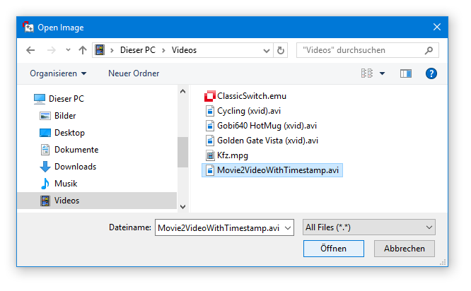
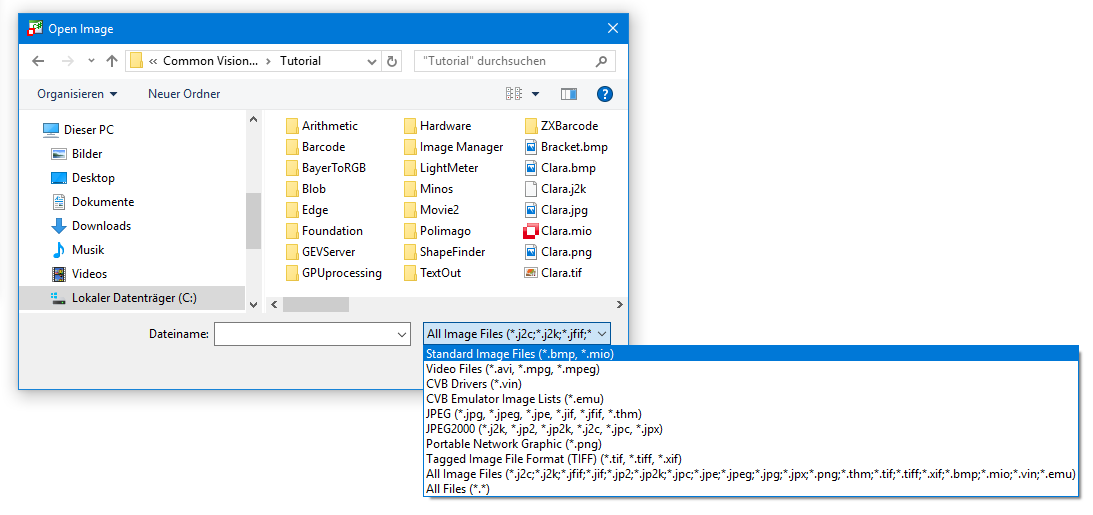
The supported file formats are provided in the methods and functions for image file handling. CVB will find out the format type automatically in file names by the file name extension given. This is even possible in file selection dialogs with no corresponding file filters. How to load an image via the dialog is shown here:
Choose Image Files and you will get a list of all files in supported file formats like TIF, JPG, PCX, MIO. Then choose the desired file. That's it.
To save an image in a supported file format, enter the desired file name and the appropriate extension. The file will be stored automatically in this file format.
Related Topics
Image Control
Supported File formats
There are the core DLLs that contain the adaption of the hardware abstraction layer of Common Vision Blox for a given data source and they are commonly referred to as "drivers" or "vin drivers" in Common Vision Blox.
The Video INterface (VIN) files are used in Common Vision Blox to access different frame grabbers, cameras and other real or virtual devices. These drivers are installed to the %CVB%Drivers directory.
The set of CVB hardware drivers that is available for a given release can be found on the Common Vision Blox setup in the CVB user forum. Please visit the CVB website frequently for getting actual available driver setups for supported cameras and framegrabbers. Video interface drivers use an COM-like interface concept for their implementation and are therefore not tied to specific versions of Common Vision Blox. In other words: It is (within certain boundaries) no problem to use a video interface driver that is significantly older or newer than the version of Common Vision Blox you are using.
The majority of available vin drivers has been developed by STEMMER IMAGING. A Driver Development Kit (DDK) for implementing vin drivers is available - interested hardware manufacturers are encouraged to contact STEMMER IMAGING for details.
CVB interfaces
Find all CVB interfaces listed here in Image Manager CVCDriver.dll and CVCImg.dll.
Using Grabber Properties menu item or icon from Common Vision Blox Viewer from Start Menu or CVSysTray.exe from %CVB%Applications directory shows the Common Vision Blox interfaces supported by image when a driver is loaded:
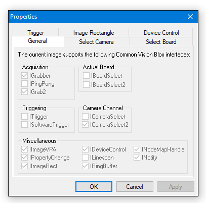
Common CVB interfaces What software interfaces do image/drivers support?
Most of these interfaces are implemented by the drivers, details are listed in each specific CVB driver documentation (%CVB%Drivers directory)
| Interface in CVCDriver.dll | Description |
|---|---|
| IBasicDigIO | Controlling IOs |
| IBoardSelect/IBoardSelect2 | Switching between different devices |
| ICameraSelect/ICameraSelect2 | Switching between different devices |
| IDeviceControl | Controlling hardware settings |
| IGrab2/IGrabber | Image acquisition |
| IImageRect | Image handling and acquisition (grab and snap) |
| IImageVPA | Image Access |
| INodeMapHandle/INodeMapHandle2 | Control of GenICam compliant devices |
| INotify | Register callback functions for events |
| IPingPong | Image acquisition |
| IRingBuffer | Recording to ram buffers |
| ISoftwareTrigger | Sending a software trigger to a device |
| ITrigger | Reacting on external triggers |
For details using these interfaces refer CVCDriver.dll and CVBImg.dll description. Tutorials with examples how to use these interfaces to access devices and process images can be found in
Specific CVB interfaces
| Interface in CVCDriver.dll | Description |
|---|---|
| ILineScan | Special features for controlling line scan cameras |
| IPort | Only AVT FireWire driver |
| IPropertyChange | Dalsa Genie driver, AVT driver |
| IRegPort | GenICam driver only |
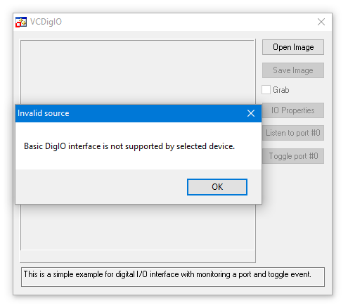
Register bits for I/Os can be controlled via the CV Digital IO-Control or by using the IBasicDigIO functions of the CVCDriver.dll . Find functions for checking available input and output ports, states of them and groups of ports. Also it can be verified whether the image supports the BasicDigIO interface.
For testing purposes, please use the CVB Image Manager Tutorial VC Digital IO Example (in %CVB%Tutorial directory) .
If the IBasicDigIO interface is not supported by the used driver, then it is indicated while loading the driver :
The IBoardSelect2 interface allows to switch between different connected image acquisition devices (frame grabbers or cameras). CVB handles device switching via the IBoardSelect2 functions of the CVB Driver Library or the Board property of the CV Grabber Control.
For testing purposes, please use the CVB Image Manager Tutorials (in %CVB%Tutorial directory) :
VC Sizeable Display (button Show Grabber properties) to access IBoardSelect and IBoardSelectSelect2 properties and methods.
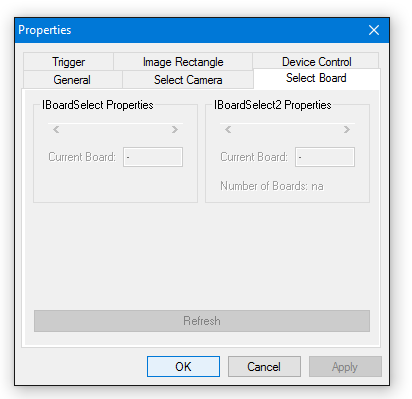
or VC Pure DLL/VC Driver example (menu Edit item Image Properties).
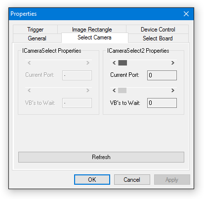
ICameraSelect2 Interface: switching between different devices
The ICameraSelect2 interface allows to switch between selected camera ports or image acquisition devices. The switching between devices is realized in CVB via the ICameraSelect2 functions of the CVB Driver Library using CS2Get... and CS2Set... or with CamPort property of the CV Grabber ActiveX Control. To test the basic functionality, please use the Common Vision Blox Viewer (button or menu item Show Grabber properties).
Access ICameraSelect and ICameraSelect2 properties and methods:
A platform independent C++ code example can be found in the MultiOSConsole example (Camera.cpp) of the Image Manager
Windows: %CVB%Tutorial\Image Manager\VC\VCMultiOSConsole
Linux: /opt/cvb/tutorial/ImageManager/ComplexMultiOSConsoleExample
IDeviceControl Interface: controlling hardware settings
The IDeviceControl interface offers the possibility to set or change hardware (i.e. camera) parameters directly over CVB.
The IDeviceControl Interface can be accessed through DCStrCommand and DCBinaryCommand function of the CVB Driver Library or over CV Grabber ActiveX Control - SendStringCommand or SendBinaryCommand method.
The complete list of available command values can be found in the driver specific iDC_*.h header file. Refer always to the CVB Driver User Guide for your image acquisition device to check the list of supported interfaces. It contains all IDeviceControl definitions for the VIN driver for use with DCStrCommand and DCBinaryCommand functions of the Image Manager as well as the SendBinaryCommand and SendStringCommand methods of the grabber ocx.
Often used command strings are listed here:
DC_BUFFER_INFO_TIMESTAMP
This is the time stamp received from the acquisition hardware saved to the acquired buffer in the memory.
DC_BUFFER_INFO_IMAGEID
This is the image id received from the acquisition hardware saved to the acquired buffer in the memory.
DC_BUFFER_INFO_NUM_PACKETS_MISSING
This is the number of missing packets from the image transfer of a GigE Vision camera related to the acquired image of the currently used buffer.
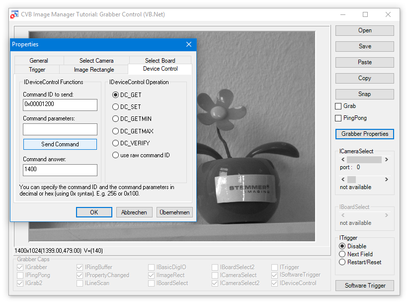
Command ID can be tested over the Grabber Properties window in CVB Viewer or over CVB Image Manager Tutorials VC Sizeable Display example, VBGrabber.NET or one of the following code examples.
For GenICam vin driver use the iDC_GenICam.h in %CVB%Lib\C
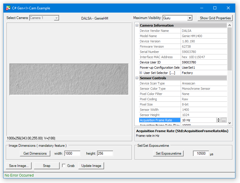
Send command DC_BUFFER_INFO_DELIVERED_WIDTH = 0x00001200, Command Answer results 1400, this is the delivered image width value of the connected GenICam device.
VC++ Example Code: retrieve ImageID (from the VC++ GenICam Simple Demo)
VC++ Example Code: retrieve lost packets from last frame
DCBinaryCommand function sends the binary command directly to the CVB driver.
It has to be called twice when working with output buffer size (first call with iInBufSize NULL and second call with resulted iOutBufSize as iInBufSize).
If you use the CV Grabber Control, the SendStringCommand method is similar to the DCStrCommand function of the Driver Dll.
IDeviceControl Commands Beside accessing all different parameters by the GenApi interface some other commands are supported to give extra information.
DC_DEVICE_PORT_NODEMAP
returns the node map handle of the camera xml. This handle is returned when the configuration generates a valid GenApi xml file.
If no valid xml file could be found a NULL pointer is returned.
A custom xml can be used by defining it in the ini file.
DC_DEVICE_NODEMAP
returns the Nodemap handle to the DMA/Board xml.
This handle is returned when the configuration generates a valid GenApi xml file.
If no valid xml file could be found a NULL pointer is returned.
A custom xml can be used by defining it in the ini file.
These commands return special single values:
DC_BUFFER_INFO_TIMESTAMP
this command returns the time stamp of the last frame buffer acquired in µs.
DC_BUFFER_INFO_IMAGEID
frame ID is the number of the acquired image frame increased in steps of 1. Starts with 1.
IGrab2/IGrabber Interface: image acquisition
The IGrab2 interface was designed to do a continuous image acquisition into a image ring buffer and to be able to protect certain image buffers against overwriting. It provides functions for starting and stopping the acquisition, wait for an image, etc. and belongs to the CVB Driver Library. All functions of this IGrab2 interface are also used by the CV Image Control if you start an acquisition by setting it's Grab property to TRUE.
The function G2GetGrabStatus with its options offers information about the image acquisition which can be used for monitoring and analysis.
Option examples:
G2INFO_NumPacketsReceived
This is related to GigE and indicates the number of data packets received on the GigE Vision streaming channel.
G2INFO_NumResends
This is related to GigE and indicates the number of resend requests issued by the host. If this number increases, it indicates that something is wrong with the data transmission. Possible reasons may be: Settings of the network card, CPU-load on the host, cable/switch problems, bandwidth problems on the Link.
and much more.
A platform independent C++ code example is the MultiOSConsole example (Camera.cpp) of the Image Manager
Windows: %CVB%Tutorial\Image Manager\VC\VCMultiOSConsole
Linux : /opt/cvb/tutorial/ImageManager/ComplexMultiOSConsoleExample
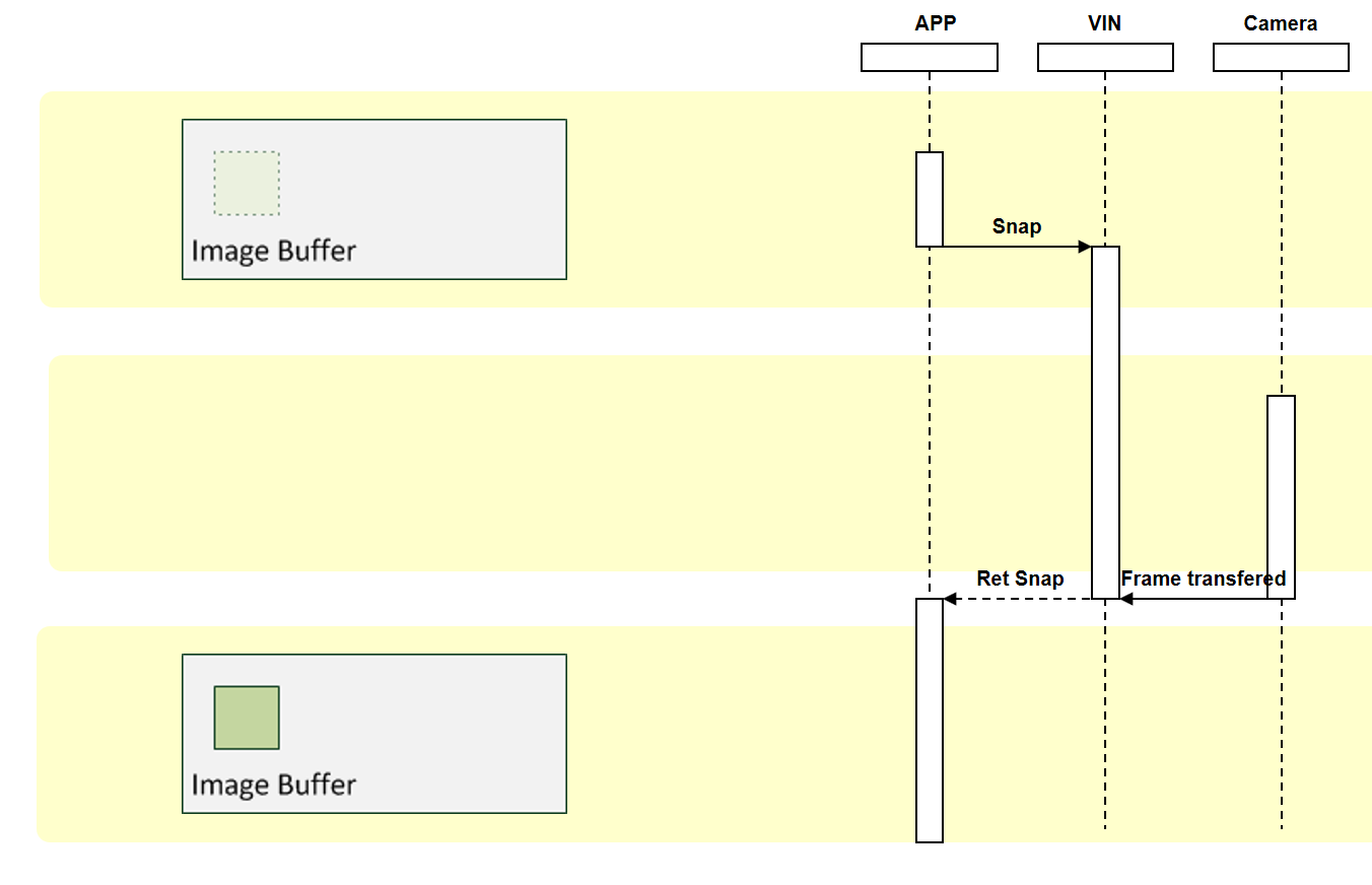
The IGrabber interface is used for single image acquisition functions (snap).
Option examples:
IPingPong description - image acquisition
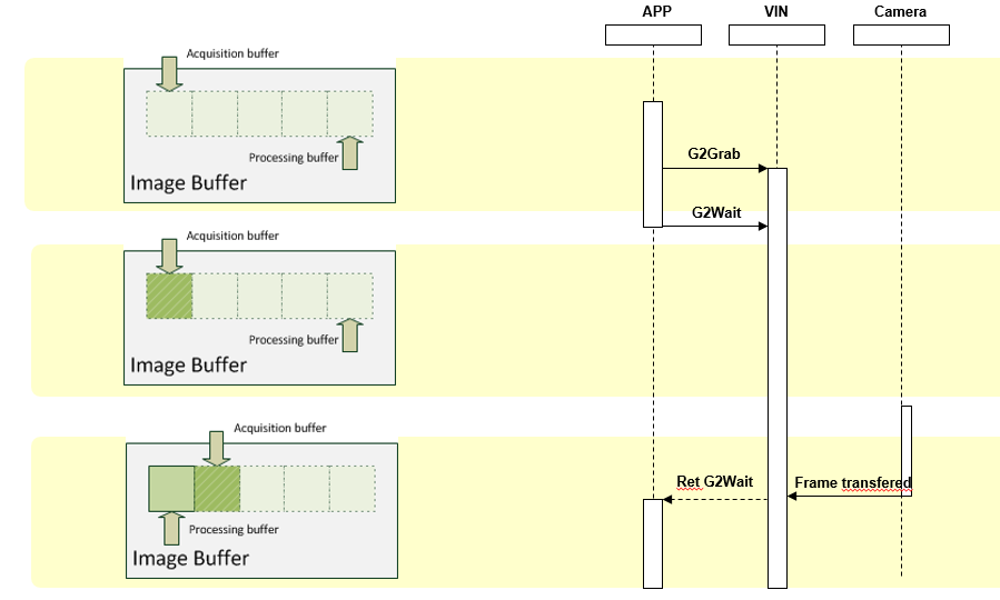
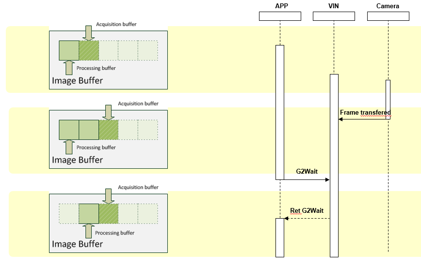
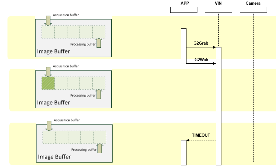
The IPingPong interface implements an asynchronous image acquisition with two buffers. All functions of this interface are also used by the CV Image Control if you start an acquisition by setting its Grab property to TRUE. In CVB, this can be implemented via the PingPong functions of the CVB Driver Library or the Grab property and Snap method of the CV Image Control.
A description of these interfaces can be found in the Common Vision Blox Manual. For testing purposes, please use the CVB Image Manager Tutorials VB.Net Ping Pong example or the VCPureDLL/VCDriverMDI example (menu Edit-PingPong Grab) or any other CVB Tutorial program .
Modern image acquisition devices can support more than 2 buffers using the IGrab2 interface.
All functions of this interface are also used by the CV Image Control if you start an acquisition by setting its Grab property to TRUE.
IImageRect Interface description: image resolution changes
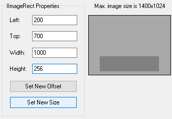
Some cameras or other devices allow the user to read out a reduced size image or parts of an image, so this interface can be used to change the resolution of the image or to inform the driver for resolution changes made previously in the hardware.
Changing Resolution over IImageRect
For cameras allowing to read out a reduced size or parts of the image this can be used with the IImageRect Interface. The settings can be adjusted with the
Inform the driver about changed resolution or pixel format
With GenICam compliant cameras settings as resolution, pixel format and - if supported - binning or partial scan, can be changed in the camera directly. This can be done either with a control tool or the node map interface. If one of these settings is changed, the image object has to be updated.
You can restart the application or inform the driver about the changed resolution or pixel size. This is necessary as the underlying image object holds preinitialised buffers where the image stream from the camera is written to. When the size of the image changes the underlying image object need to be informed and the buffers need to be reinitialized.
To do that you need to:
C# Example Code:
For testing, please use the Common Vision Blox Viewer or CVB Image Manager Tutorials VCPureDLL/VCDriverMDI example or VB Grabber OCX.
The IImageVPA interface provides rapid access to image pixels in cases where the image is represented in memory in some VPA-compatible format. In addition to the usual QueryInterface, Addref and Release, IImageVPA contains the following functions:
ImageDimension
Returns the dimension of the image object, i.e. the number of image planes. The image planes are accessed by an index and all indexed functions below are defined for
0 <= Index < (IMDimension - 1).
ImageWidth/Height
Logical width and height of the image. This is how wide and high the image should appear to the processing software. All planes of the image have this logical width and height which needn't match their actual width and height in memory - SourceWidth and SourceHeight below.
Virtual image dimensions can be used to control aspect ratios of non-square pixel frame grabbers or for pyramids.
ImageDatatype(Index)
Returns the data type of a pixel value in the image plane given by Index. The format for the encoding of data types should include the bit count (8-bit is probably the most frequent) and flags to specify signed or unsigned numbers or possibly floating point numbers where there is any ambiguity (e.g. for 32 bits). Our proposal is to use a Dword to identify the data type where the lowest byte defines the bit count and bits 8 and 9 stand for signed/unsigned and float/integer, respectively. Higher bits are free to implement user-specific flags (i.e. ColorBGR, as may be desired for one of the examples presented).
ImageVPA (Index)
Returns the address of the VPA table for the Index-th image plane and the base address of the image plane. The VPA table is an array of simple 8-byte structures containing the two Dword fields XEntry and YEntry. Details on the size of this array and its precise definition follow in the complete definition of the interfaces.
GetImageCoords/SetImageCoords
Sets and returns the current coordinate system. The coordinate system is defined by the origin and a 2x2 matrix which represents scaling and rotation.
These functions are implemented in a semantically correct way if the scalar value of the pixel (X, Y) in the Index-th image plane can be addressed using the following equation:
Address := BaseAddress (Index) + VPAT (Index)[X].Xentry + VPAT (Index)[Y].YEntry.
The following figure shows the mechanism of pixel addressing with VPA without using the coordinate system:
The following figure shows the mechanism of pixel addressing with VPA using the coordinate system:
Suppose that for some processing routine the index of the image plane in question has been fixed, and that the two pixel coordinates (X, Y) reside in the general registers (ecx, edx) and the value of VPAT in ebx. Then the assembler statements
mov eax, BaseAddress ; load base address
add eax,[ebx+8*ecx] ; add XTable(X) - scaled addressing
add eax,[ebx+8*edx+4] ; add YTable(Y) - scaled addressing
compute the pixel address. This involves a minimum of 5 processor cycles (no cache miss on BaseAddress and the tables). Three cycles are to be added if the VPAT and the coordinates have to be moved to memory first.
INodeMapHandle Interface: access to the Nodemap
This interface is used to obtain access to the Device NodeMap. INodeMapHandle interface is part of the CVB Driver Library and provides functions to set and retrieve values from the NodeMap for the current device (e.g. a GigE Vision camera).
Sample Code in C++
For testing purposes, please use the CVB GenICam Tutorial: VCSimpleDemo or CSGenICamExample (%CVB%Tutorial\Hardware\GenICam).
INodeMapHandle2 Interface description: access to different Nodemaps
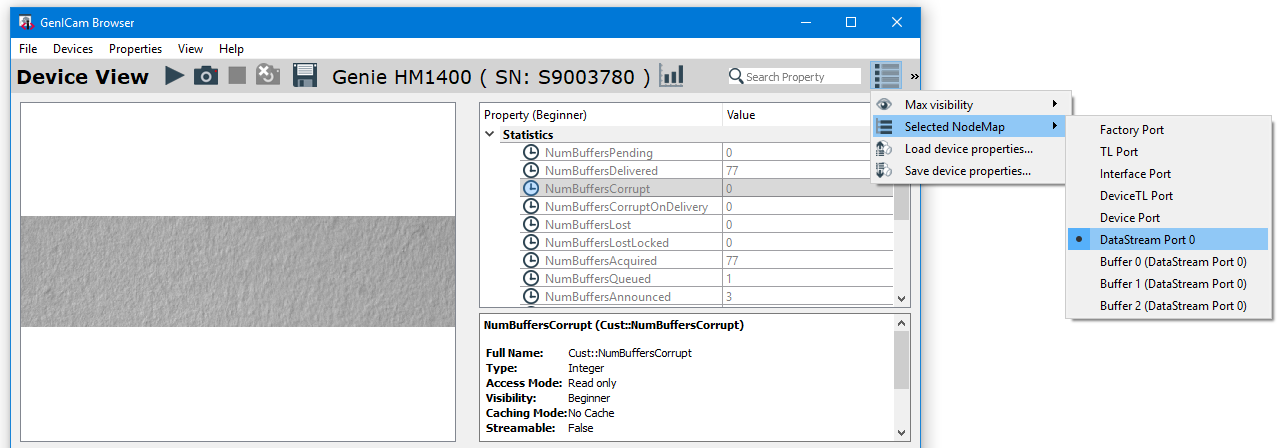
A GenICam transport layer (GenTL) exports a number of separate NodeMaps to access logical parts of the driver. Beside the well known Device Nodemap a GenTL Producer provides a NodeMap to configure the DataStream and to get statistical data. Other technologies might as well have multiple NodeMaps. INodemapHandle2 interface is part of the CVB Driver Library and allows to enumerate the various NodeMpas and to get access.
NodeMap access can be used inside GenICam browser:
INotify Interface description: callback functions for events
The INotify interface allows to register callback functions for events like disconnect/reconnect or events generated by the device. In case such an event carries additional data, it is passed to the callback function.
VC++ Example Code:
C# Example Code:
Connection Monitoring using the INotify interface Within our GenICam architecture it is possible to be informed if a device disconnects or reconnects. This is called Connection Monitoring and is supported with GigE Vision.
This feature can be useful if a device temporarily loose its power and the connection needs to be re-established. The Connection Monitoring is realized over the INotify interface with its DEVICE_DISCONNECTED and DEVICE_RECONNECT event. For details refer INotify interface description.
Important Notes:
IRingbuffer Interface : image acquisition using RAM buffers
The ring buffer was designed to do a continuous acquisition into an image ring buffer. It protects image buffers against overwriting and can buffer several images if the following processing takes longer than the image acquisition for a short period of time. The ring buffer is used automatically with every CVB image acquisition and a default size of 3 buffers. It is recommend to use a value around the expected framerate so that a period of one second can be buffered. This can be modified in the option settings of the GenICam Browser.
The IRingbuffer interface can be used to modify the number of used buffers programmatic. It supports also other ring buffer modes. The access to the IRingbuffer interface can be done in CVB via the
For testing purposes, please use the CVB Image Manager Tutorials : VCRingBuffer or CSRingBuffer example.
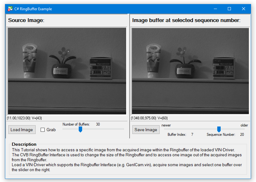
ISoftwareTrigger Interface description - software controlled triggering
The ISoftwareTrigger interface permits the sending of a software controlled Trigger to the camera without any external trigger signal. To use the software trigger the camera or device has to be set to software trigger. 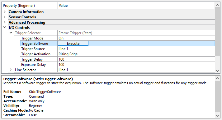
The camera configuration can be customized with the GenICam Browser. In CVB the trigger feature is set with the
For testing purposes, please use the CVB Image Manager Tutorial VC Driver MDI example (VCPureDLL). Please follow these steps:
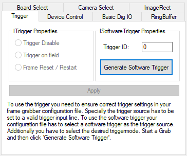
ITrigger Interface and Trigger Modes
The ITrigger interface enables the user to send an external trigger signal. The camera or device therefore has to be set to accept an external trigger. In CVB, the trigger is fired using the SetTriggerMode function of the CVB Driver Library or via the Trigger mode property of the CVGrabberControl.
For testing purposes, please use the CVB Image Manager Tutorials VC Sizeable Display or the VC Driver Interfaces Example (menu Edit item ImageProperties) in %CVB%Tutorial\ImageManager directory.
ILineScan description - special features for controlling line scan cameras
The ILineScan interface is used to control the exposure time, resolution, size and most importantly the acquisition from line-scan cameras. The functionality of this interface can be used either trough the CV Linescan Control or through the CVB Driver Library.
IPort description
Currently, the IPort interface is only used with the CVB, AVT FireWire camera driver.
A description of this can be found in the User Guide for AVT FireWire cameras.
IPropertyChange description
The IPropertyChange interface is used when a property of the image is about to change or has been changed. In CVB, this is accessible via the IPropertyChange functions of the CVB Driver Library or the ImagePropertyChanged event of the CVGrabberControl.
For testing purposes, please use the CVB Image Manager Tutorial VCPureDLL/VCDriverMDI example.
IRegPort description
The IRegPort interface provides low level access to the current device. It is recommended that you use the high level interfaces e.g. handled by the CV GenICam Control.
The CVMock.vin virtual driver is a driver which can be loaded as .vin driver instead of a camera driver. It then either loads an image set or an EMU file from disk or generates its own image. In contrast to the EMU format, a wider range of device options is supported an can be accessed programatically. In this manner a camera device can be simulated for testing and coding without the actual device present. The driver can be found under %CVB%drivers. When the driver is loaded, first the working directory is checked for a valid CVMock.ini file. If none is found, the driver's configuration file from %CVBDATA%drivers is loaded. The configuration file consists of sections containing a number of settings. A section is defined in squared brackets.
Currently, two section types are used: Options and Board/Channel configuration.
Options:
Main settings to customize the driver for own image acquisition.
BoardX_ChannelY :
Emulates a capturing devices board and channel with custom parameters. For this mockType=0, an image is created from the CVMock itself which will show a roll from minimum to maximum available pixel intensity depending on the selected buffer format. A Mono8 buffer format for example will produce a monochrome roll over the buffers ranging from 0 to 255 in value. This option will be loaded when mockType=0. Following parameters can be customized:
An EMU file is a simple text file defining a number of images to be loaded. Using the IGrabber interface the application can 'acquire' from the image list. Of course all images must have the same size and the same number of planes. The file consists of a number of sections containing a number of settings. A section is defined in squared brackets. Currently two sections are used: General and Files.
General:
Within General two settings are defined Delay and LoadAtOnce.
Files:
The files to be used are defined in the Files section. Within the section you might define a number of files to be loaded using the FileX (X = {1...65535}) settings.
A file is specified by it's full path.
To use any environment string you can specify it's name with leading and tailing % (e.g. %CVB%).
To specify the application directory use @APPDIR. Use @LISTDIR to specify the directory of the EMU file.
Samples:
File1=%CVB%Tutorial\*.bmp
File2=@APPDIR\clara.bmp
File3=@LISTDIR\rot*.bmp
The following is an example used to load all bitmap files from the directory of the EMU file starting with rot:
The example defines a frame time of 50ms and all images are loaded at startup (general):
Delay = 50
LoadAtOnce = 1
[Files]
File1 = @LISTDIR\rot*.bmp
Control via the Digital IO Control:
For control tasks like changing the frame rate the DigIO control of the EMU- driver has been used. The two relevant methods of the DigIO control are:
| SetOutDWORD | sets a delay in ms | DigIOControl.SetOutDWORD (0, lDelayValue, 0); |
| GetInDWORD | retrieves the actual delay value in ms | lDelayVlaue = DigIOControl.GetInDWORD (0); |
The values for the Parameters Port and Mask are always 0.
Related Topics
None
Sample Code in VC
Examples
| Visual Basic | |
| Visual C++ | VCEmu |
This driver realized via the CVBAvi.dll enables access to DirectShow compatible video files via the IGrabber interface of Common Vision Blox. If the file extension is unknown to the Image Manager function LoadImageFile it automatically loads the CVBAvi driver, the driver then loads the video if it recognizes and supports the video file format.
Supported Video files
Supported Interfaces
How to open a video file
Settings and Control of a video file
The default supported video container formats are *.avi and *.mpg files. But especially the *.avi container format can have different types of video streams (e.g. DivX, Xvid). If these video streams are supported depends on the codecs installed on your system. For example after installing the DivX codec on your machine, this driver is also able to playback DivX encoded video streams.
Additional video decoders
For other video streams Windows 7 and newer use the Microsoft DTV-DVD Decoder which is part of the Windows installation. This decoder is incompatible with CVB. Because of this other video streams like H.264 are not supported with CVB on Windows by default. The Microsoft DTV-DVD Decoder has to be disabled and another decoder like the LAV Filters or ffdshow filter has to be installed to support other video streams like H.264. To disable to Microsoft DTV-DVD Decoder search with your favorite search engine in the internet "How to Disable Microsoft Windows 7 built-in Microsoft DTV-DVD Decoder".
A Video file ( eg. AVI or MPEG) could be opened via every LoadImage functionality in CVB.
In this case it is opened via a Dialog box :
Methods and functions for loading images
Image Control- LoadImage method
Image Control- LoadImageByDialog method
Image Control- LoadImageByUserDialog method
Image Library- LoadImageFile function
Supported Interfaces
The CVB driver interfaces are implemented by the Driver DLL with
| IGrab2 | Image acquisition |
| IImage | Image handling and acquisition (grab and snap) |
| IGrabber | Image acquisition |
| IBasicDigIO | Controlling the videofile for Playback, goto a dedicated framenumber and more |
| IDeviceControl | Controlling the videofile for Playback, goto a dedicated framenumber and more |
| INotify | Registration of user defined callbacks for asynchronous driver events. In this case access to Metadata. |
and as a number of CVB ActiveX Controls such as the
CV Image Control,
CV Grabber Control,
CV Dig IO Control.
The documentation for all possible configurations can be found in the Common Vision Blox Manual in the Image Manager chapter.
The interfaces and the registry entries allow to deal with Videofiles. With this it is possible to create a simple Videoplayer by your own like it is shown in the following screenshot:
The player could:
The details how this could be handled are explained in the following chapters.
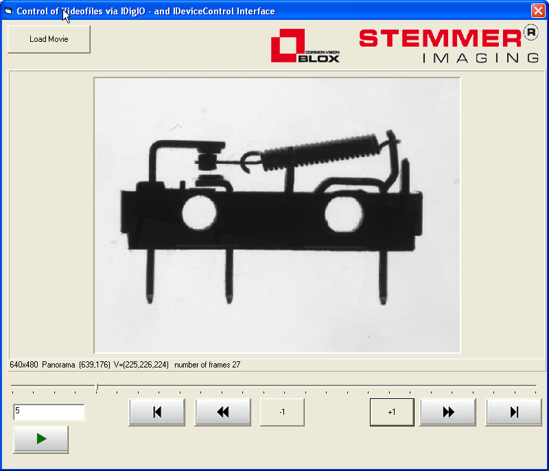
For control tasks that can not be handled with the built-in Grabber Interface of CVB, the DigIO interface of the CVBavi driver has been used. The functionality could be implemented via the DigIO functions of the Driver Dll or the via the CV DigIO Control.
The driver has 32 inputs and 128 outputs that are mainly addressed as dwords. The following tables describe the meaning and use of those portgroups and bits:
Digital INPUTS of the CVBavi driver
| Portgroup | Bit | Use | Notes |
|---|---|---|---|
| 0 | 1..32 | Gives the number of frames in the video file | - |
Digital OUTPUTS of the CVBavi driver
| Portgroup | Bit | Use | Notes |
|---|---|---|---|
| 0 | 1 2 3 4 5 6 7 8 9 10..32 | Advance 1 Frame Rewind 1 Frame Advance 10 Frames Rewind 10 Frames Advance 100 Frames Rewind 100 Frames Stop Playback Start Playback Rewind to first frame Unused | Portgroup 0 can only be addressed via the function SetOutBit. SetOutDWord on port group 0 is ignored. |
| 1 | 1..32 | Current Image Number | Can be used to set or retrieve the current frame number. May only be addressed via the function SetOutDWord - SetOutBit is ignored (whereas GetOutBit is working). |
| 2 | 1..32 | Volume | Can be used to set or retrieve the current volume. May only be addressed via the function SetOutDWord - SetOutBit is ignored (whereas GetOutBit is working). Allowable values for the volume are according to DirectShow conventions between -10000 (mute) and 0 (maximum). |
| 3 | 1..32 | Balance | Can be used to set or retrieve the current balance. May only be addressed via the function SetOutDWord - SetOutBit is ignored (whereas GetOutBit is working). Allowable values for the volume are according to DirectShow conventions between -10000 (left) and 10000 (right). |
Typical statements under Visual C++ would thus look like this:
Note: The 'Mask' parameter of the function SetOutDWORD is ignored by CVBavi). Addressing the single bits of port group 1 to 3 does not make sense and therefore is ignored by the driver. Default parameters for volume and balance can be supplied in the registry (see below).
Although it is in principle possible to access the same virtual image acquisition device from several images, we do not support this, it is completely impossible when using Live-Replay . In Single-Frame mode it works, but when n instances of a driver access the same virtual image acquisition device simultaneously, each instance only gets every n-th frame of the video stream. Before switching to a different virtual board we strongly recommend stopping any background replay by calling a single Snap on the images in question.
When using the Single-Frame mode please keep in mind that some codecs support the IMediaSeeking Interface but do not deliver still images, instead they always give back the last key frame (DivX 4 is an example of this behavior). In those cases, working in Single-Frame mode may be dissatisfying.
There are some more features available than with the Digital IO Interface using the IDeviceControl Interface via the IDeviceControl functions of the Driver Dll or the CV Grabber Control. The features are:
DC_VOLUME = 0x00000100, // not supported when there is no audio stream in the AVI
DC_BALANCE =0x00000101, // not supported when there is no audio stream in the AVI
DC_FRAMENUMBER = 0x00000102,
DC_TOTALFRAMENUMBER = 0x00000103,
DC_REPLAYRATE = 0x00000104,
DC_POSITION = 0x00000105,
DC_TOTALTIME = 0x00000106,
DC_JUMPRELATIVE_FRM = 0x00000107,
DC_JUMPSTART = 0x00000108,
DC_FRAMETIME = 0x00000109,
DC_JUMPRELATIVE_TIM = 0x0000010A
see header file for Visual C the IDC_AVI.h in the CVB\Lib\C directory.
Example code in Visual Basic for retrieving the total framenumber of an AVI-File looks like this:
CVgrabber1.SendStringCommandEx &H103, DC_GET, " "
For sure it is also possible to get the information interactively via the CV Grabber Control like here the Framenumber of the current frame is retrieved ( DC_FRAMENUMBER = 0x00000102)
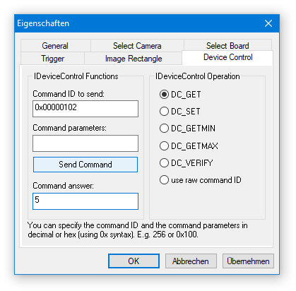
The function GetModule from CVCDriver.DLL returns the following parameters when used on CVBavi:
pGraphBuilder Handle for the IGraphBuilder Interface
pMediaControl Handle for the IMediaControl Interface
pBasicAudio Handle for the IBasicAudio Interface
In the GetModule call, AddRef is called on all the returned handles (except if the returned handle is NULL). Therefore you should - as normally when programming COM - call Release on them whenever you no longer require the resource.
The function GetModule is used as follows:
Microsoft Visual Basic:
Dim pGraphBuilder as
Long Dim pMediaControl as Long Dim pBasicAudio as Long GetModule(cvImg.Image,pGraphBuilder, pMediaControl, pBasicAudio)
Microsoft Visual C++:
IGraphBuilder
*pGraphBuilder; IMediaControl *pMediaControl; IBasicAudio *pBasicAudio; GetModule((IMG)m_cvImg.GetImage(), 1(void**)&pGraphBuilder, (void**)&pMediaControl, (void**)&pBasicAudio);
Meta data are (ANSI-) strings with up to 64k characters, one per image being recorded. Meta data can be written with the CVB Movie2 Tool. For example, the MetaData can be used to save the corresponding timestamp as a string for every recorded frame within the AVI container. To read out the MetaData you can implement the CVB Notify Interface (INotify) of the Driver.dll in your own application. If you prefer the CV Grabber Control you can use the ImageNotificationString Event. As examples the VCMovie2PlayerExample and the CSMovie2PlayerExample are included in Movie2.
Please note that some media players may get confused by the presence of a text stream in the AVI container. When an AVI Editor does not support the text stream the MetaData is lost after editing the AVI file. For Example VirtualDub with DirectStreamCopy writes only the text of the first frame to all other frames.
The supported INotify Event is CVNO_EID_METADATA_CHANGE which is fired when new Metadata has arrived.
Following StatusCommands are supported with NOGetStatus:
e.g. if you want to check if MetaData is available for your loaded avi file use CVNO_INFO_IS_AVAILABLE:
Sample Code in CSharp
Sample Code in VC
The description and the functions of the INotify Interface are described in Driver Dll. Example Code can be found in the INotify Callback description.
There are some parameters which could be set via a Registry entry. Please create a registry entry in ..Software\Common Vision Blox\Image Manager\AVI
| NumBuffers = 2 | Sets the Number of Buffers.Values from 2 to 256 |
| DefaultVolume = 10000 | Volume for video playback (can be changed via the DigIO Interface during playback). Valid values range from 0(mute) to 10000 (max). If this parameter is omitted, 10000 is assumed by the driver. |
| DefaultBalance =10000 | Balance for video playback (can be changed via the DigIO Interface during playback). Valid values range from 0 (left) to 20000 (right). If this parameter is omitted, 10000 (center) is assumed by the driver. |
Note: The former INI-file CVBAvi.ini is obsolete.
Common Vision Blox provides two different types of Areas of Interest (AOIs):
Frames are rectangles with horizontal and vertical edges. Frames are used by CVB Tools or functions which are restricted to use areas with horizontal and vertical edges and no rotation.
For further information, you can look up for example the function CreateImageMap.
Refer Tutorial: %CVB%Tutorial\Image Manager\VB.NET\VBMapper.NET
One rectangular frame is defined by 2 points: the Left Top (LT) and the Right Bottom (RB) corner points along with their positions SrcLeft, SrcTop, SrcRight, SrcBottom. The type declaration of frames is built analogically to the Windows RECT structure:
| Type TDRect Left As Double Top As Double Right As Double Bottom As Double End Type |
|
The frame coordinates can be extracted with the Display control method GetSelectedArea. Please take in mind that this method returns the TArea Structure with 3 points. Dragging frames with the mouse causes RectDrag or RectDraged events being created from the Display control.
See the sample code below.
Sample Code:
Areas are parallelograms with any desired angle. Areas are used by a lot of CVB Tools or functions.
For examples, look up the function ImageHistogram.
Refer Tutorial: %CVB%Tutorial\Image Manager\VB.NET\VBRotateArea.NET
Parallelograms are defined by three vectors with respect to the origin of the coordinate system (CS Origin): P0, P1 and P2 with their positions X0, Y0, X1, Y1, X2 and Y2 respectively. Therefore, adjacent edges do not have to be perpendicular to each other. Such parallelograms cannot be drawn up with the mouse, only by programming.
The type declaration for areas is:
| Type TArea X0 As Double Y0 As Double X1 As Double Y1 As Double X2 As Double Y2 As Double End Type |
|
Areas can also be created by use of the SetSelectedArea method of the display control.
The area coordinates can be extracted with the GetSelectedArea method of the Display Control . Areas can be dragged, rotated or changed interactively with the mouse. This causes events of the types AreaDrag or AreaDraged being sent from the Display control.
To convert a rectangle with 2 corner points to a TArea structure with 3 points, use the function SetRectArea.
There are special cases where the user has to convert an Area in a TDRect structure. A common way to achieve this is to use the smallest rectangle which completely encloses the area. This task has to be implemented in user functions.
In CVB, the CreateSubImage function is declared with an area as input parameter Area. This function converts the Area internally to the bounding rectangle.
Related Topics
Image Control - Property Pages
Display Control - Property Pages
Area Functions
Coordinate System, Origin and Areas
This section outlines some additional information for using Common Vision Blox according to
Density
2D Transformation Matrices
Density specifies the sample rate of the image. A density of 1000 means that all pixels in the specified area are used in the algorithm. Where as a density of 500 means that only every second pixel is used. Note that the used pixel is NOT interpolated.
This is used by some Image Manager functions (like ImageHistogram), methods as well as by some Common Vision Blox Tools.
Transformation matrices are used by some Image Manager functions (like CreateMatrixTransformedImage as well as by some Common Vision Blox Tools, e.g. Minos. See also the type definition of TMatrix and the chapter Areas and Matrices.
The Image-dll provides an affine transformation from xy to x‘y‘ coordinate system :
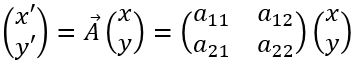
where is the affine transformation matrix (e.g. TMatrix).
The following equations show all affine transformation:
Reflection/Mirror
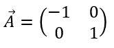
Scaling
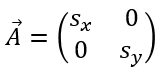
where are the scaling factors in x and y.
Rotation
where α is the rotation angle about the origin.
Shear
If no shear is present, and the image is not reflected, the transformation matrix is:
then the scaling and the rotation angle are given by:
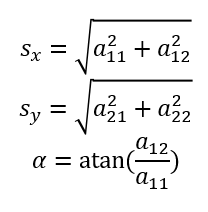
To transform from x‘y‘ to xy, the matrix has to be inverted with (e.g.) the CVB function InverseMatrix(TMatrix A, TMatrix &AInv):
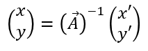
To the affine transformation a translation can be added (as for TCoordinateMap).
This can be described by the 2D homogeneous coordinate matrix
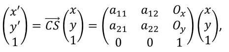
where  is the translation in x and y.
Common Vision Blox offers fast and flexible access to image data via two technologies:
VPAT - Virtual Pixel Access Table
Scan Functions
The VPA table allows read and write access to all pixels using the base address, the tables for the offset of the lines and the table for the pixel offset within a line.
GetLinearAccess
This function uses the AnalysexVPAT functions to verify if the image can support direct linear access to the data. If the function returns TRUE, it is possible to access the image data via a pointer. The function allows existing algorithms to be ported CVB images quickly and efficiently.
Note: This function is not supported in Visual Basic due to the programming language not supporting pointers.
GetLinearAccess is the preferred way to access the image data. If not available you can use VPAT Access via the GetImageVPA function.
Function description and code examples can be found here:
%CVB%Tutorial\Image Manager\VC\VCAnalyseVPAT
GetImageVPA
This function allows access to the virtual pixel access table (VPA). The VPA tables allow read and write access to all pixels using the base address, the tables for the offset of the lines, and the table for the pixel offset within a line.
Function description and code examples can be found here
%CVB%Tutorial\Image Manager\VC\VCVPAT
Using Scan Functions the scan direction and search direction can be manipulated. For example by controlling the vectors the scan direction can be changed. The first scan line is always from P0 to P1, and the scan direction is always from P0 to P2.
ScanImageUnary (DLL)
This dll-function allows access to all planes of the image taking Area and Density into consideration.
ScanPlaneUnary (DLL)
This dll-function allows access to a plane of an image taking area and density into consideration. Function description within a tutorial can be found here: %CVB%Tutorial\Image Manager\VC\VCAccess
ScanImageBinary (DLL)
This dll-function allows simultaneous access to the two different images taking Area and Density into consideration. This could be used for example to link two images via a lookup table.
ScanPlaneBinary (DLL)
This dll-function allows simultaneous access to the two different specified planes of two images taking Area and Density into consideration. This could be used for example to link two images via a lookup table.
ScanImage (OCX)
This functions gives Visual Basic users access to the ScanImage functionality.
ScanPlane (OCX)
This functions gives Visual Basic users access to the ScanPlane functionality.
The Common Vision Blox API now generally supports the use of Unicode strings almost anywhere strings can be passed into or retrieved from function calls. There are currently only three exceptions to this rule:
For all functions exported by our unmanaged DLLs/shared objects (with the exception of the aforementioned set) that accept a pointer to a zero-terminated char string, an equivalent function has been added that accepts a pointer to a zero-terminated Unicode string. These new functions have been named identical to the ones after which they have been modeled with the character "W" appended to the function name. For example:
(note that the more obvious option of simply adding a function overload was not available to us as the extern "C" declaration implied by the IMPORT macro forbids overloads).
Subtle differences in character encoding exist between the Windows™ and the Linux platform:
| Windows | Linux | |
|---|---|---|
| char | usually codepage-based character encoding | UTF8 |
| wchar_t | UTF16 | UTF32 |
These differences have been preserved and addressed:
Usage of the already existing char versions of the functions of Common Vision Blox has not changed, neither on Windows nor on Linux, and users may continue using these functions as they did before. Users who want to make use of the newly added Unicode functions, however, should be aware of the following:
C++
As previously described, the char and the wchar_t versions of the functions are directly accessible. For convenience #define statements have been added for these functions that handle mapping automatically according to the current Character Set setting of your Visual Studio project. To stick with the previous example: When working with C++ the following variants of LoadImageFile are available:
| Function | Input/Meaning |
|---|---|
| LoadImageFile | codepage-based character encoding |
| LoadImageFileW | UTF16 |
| LoadImageFileT | maps to LoadImageFileW if the preprocessor symbol UNICODE has been defined; otherwise: LoadImageFile |
C#/VB.Net
C# and VB.Net programmers have the easiest approach to using Unicode in Common Vision Blox. The type System.String has been using UTF16 all along. In the past the marshaling code has taken care of the necessary conversion to codepage strings when calling functions from Common Vision Blox managed wrappers (potentially losing the information that cannot be mapped to the current code page).
Now those conversions simply do not happen any more and at the same time no information is lost in the transition between the managed code's System.String and the Common Vision Blox function.
In other words: whenever .Net code calls e.g. Cvb.Image.LoadImageFile the unmanaged function that actually gets called is now LoadImageFileW and no changes need to be made to .Net programs for the sake of using Unicode - recompilation against the new managed wrappers is sufficient.
ActiveX Controls
The API of the Common Vision Blox ActiveX controls has not changed at all - they continue using BSTR strings internally which usually are Unicode strings. The only difference now is that if an application does actually pass an UTF16 string it will now be properly handled where before the unmappable characters have usually been replaced with '?'.
Container Formats
One particular challenge in the introduction of Unicode in Common Vision Blox was the handling of Common Vision Blox's proprietary container formats that store strings (for example the Minos Training Set or Classifier files). The aim was to preserve as much backward compatibility as possible and switching those container formats to UTF16 would have broken that backward compatibility.
Therefore a different approach was taken: The new builds of those DLLs that are affected (MinosCVC.dll, ShapeFinder.dll, Polimago.dll) now always store UTF8-encoded strings in their containers - making it generally possible to open these containers also in the older builds of those tools. In the newly saved containers, the encoding is identified by a prepended BOM (Byte Order Map). So when opening containers saved with the new builds of these DLLs in an older version, you will notice three extra characters ("" - byte sequence 0xef 0xbb 0xbf) in front of each string. These characters may be safely removed or skipped. Characters beyond the ASCII range, however, are likely to have been modified during the UTF8 conversion. The other way round, if one of the new Unicode-capable DLLs loads an older container file, the strings contained in it will automatically be converted to their proper internal representation used during runtime.
In other words: Older files may be opened just like before.
CVB Webstreaming is a modular library for image conversion/compression and image transport.
The 2 modules are:
First a converter has to be created with CVB, which holds the configuration of the image conversion.
Valid Inputformats:
*These image formats will be automatically converted to the corresponding 8 bit variant.
Output formats:
The API for the converter does NOT allow passing images to the converter directly, this is internally done via the transport server. The API for the converter does NOT grant access to the converted images. Instead the converter is passed to the transport server (i.e. shared ownership), who controls the converter.
Example (with Jpeg compression):
NOTE: Each converter should only be passed to one server.
The image transport is handled via the server. Currently the each server will use the websocket technology for transporting data. More transport technologies are in development, such as RTP. At creation the server will need all needed information regarding the transport of data as well as the previously created converter.
Example (websocket with the converter from above):
With the created server and the acquired image(s), the user may start synchronous or asynchronous streaming. With the synchronous streaming the function will return once the images was successfully transmitted. Using the asynchronous streaming, the user does not know, when the image is sent.
The image handle given to the sending function can be discarded after the call, i.e. the server either has made a copy or has finished compression/conversion. In other words the compression/conversion is always synchronous.
Example (with sync sending):
The CVB Webstreaming implementation does NOT provide a client for receiving. This is a deliberate choice. There are multiple easily available APIs for Websockets.
Example (Javascript, not a complete example):
Example (C++ with boost::beast)
Object lifetime
The server and converter must be released after usage, to avoid leaked handles.
API / Library location
Header:
Library:
A destructive overlay in the image affects the image data itself.
In CVB it is done by transforming the active image in the display object into an overlay-capable image format. The transformed image then has only a 7-bit dynamic in each image plane. The lowest bit of each image plane is reserved for the overlay and preset by 0.
As soon as one overlay bit is set to 1 the overlay becomes visible. The overlay is shown in blue as here in the example %CVB%Tutorial\Image Manager\VC\VCDemo:
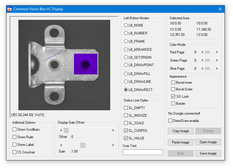
Interactively it is possible to draw rectangles ( LB_DRAWRECT ), lines (LB_DRAWLINE) or points (LB_POINT) and for sure combinations of this. In a program every pixel of the overlay could be set as described in the chapter programming destructive Overlays.
Destructive Overlays are available in all the supported visual development environments. Functions from Image Library or Display Control methods and properties can be used.
The CVImg.dll has a set of functions to deal with destructive Overlays.
CreateOverlayImage
CreateGenericImage
CreateOverlayFromPixelList
CopyOverlay
IsOverlayObject
HasOverlay
CreatePixelListFromOverlay
The Display Control has properties and methods enabling the user to use destructive Overlays.
Please see also Display Control Introduction showing destructive Overlay and the Datatype method of the Image Control.
Properties
Display
LeftButtonModes
Methods
MakeOverlayImage
Common Vision Blox supports a variety of non-destructive overlay types:
Labels, User Objects and Overlay Plug-In Objects.
Labels are available in all the supported visual development environments, however Visual Basic has some fundamental limitations that do not allow support for User Objects. The Overlay Plug-in objects were developed specifically to overcome the limitations of Visual Basic and allow a developer to use overlays in a fast, efficient and flexible way.
A detailed description of each of the available overlay object types is found on the following links:
Labels
User Objects
Overlay Plug-In Objects
Overlays of any type are identified by an object ID. This ID can be used in further functions to find the position and to move, highlight or remove the object.
It is the responsibility of the developer to track the ID's used for creating overlays and verify that each ID is unique.
Common Vision Blox allows multiple objects with the same ID to be created, however if the user requests information using this ID then CVB will return the information for the first object found with a matching ID. If CVB verified every object ID was unique before creating it then the application could become very slow, if the user created hundreds or thousands of overlays then the verification process would require a lot of processing time.
Labels can be added to any Display Control and contain a single string of text. The text, colour, position, ID and the ability to drag the label can all be defined when the label is created. Internally in CVB the label is defined in Windows coordinates and therefore, when the display is zoomed, the label remains located on the same pixel but does not zoom with the data. The text font and size are also fixed.
Please see Object ID's below for further information on assigning label ID's.
Properties, Events and Methods of the Display control regarding Labels
| Properties | |
|---|---|
| Methods | AddLabel GetLabelPosition HasLabel HighlightLabel RemoveLabel RemoveAllLabels RemoveAllOverlays |
| Events | LabelClicked LabelDraged LabelDrag |
The Image Manager examples in %CVB%Tutorial\Image Manager VBPolar.NET and VCDemo show the use of Labels.
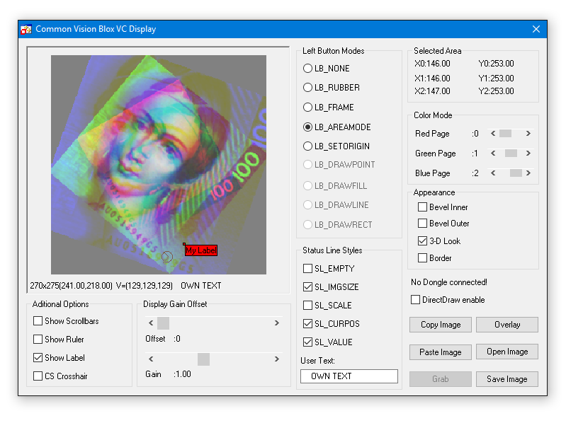
User objects are custom overlay objects designed by the application developer. Any overlay object can be described by a list of vertices defining the corner points in x,y coordinates, for example a line has two vertices, a triangle has three, but a rectangle and a bitmap graphic have only two, top left and bottom right. The number of vertices, the vertices as a list of points, and a callback function (This is not required when using the Display control) are passed to the Display control. Whenever the overlay has to be redrawn, Common Vision Blox invokes the user's callback function (Or the UserPaint event when using the Display control) which is given the position of the vertices (in window coordinates) and a device context (DC) as drawing parameters. Users can therefore draw any overlay that can be described as a list of points into the DC. The User Object overlay is not available under Visual Basic because the language does not support pointers to variable-length lists.
Please see Object ID's for further information on assigning user object ID's.
Properties, Events and Methods of the Display control regarding User Objects
The example VCOverlay shows the use of User Objects.
| Properties | |
|---|---|
| Methods | AddUserObject or AddUserObjectNET GetUserObjectPosition HasUserObject RemoveUserObject RemoveAllUserObjects RemoveAllOverlays |
| Events | UserPaint UserObjectClick UserObjectDraged UserObjectDrag |
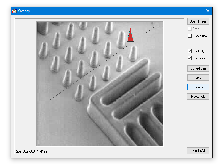
Overlay Plug-In Objects
Properties, Events and Methods of the Display control regarding Overlay Objects (OPIs)
Available Overlay Plug-Ins
Overlay plug-ins are ready-made overlays, internally the plug-ins themselves constitute user objects which draw a certain overlay object (e.g. a line or a circle). An overlay object can possess more vertices externally than it has internally as a user object, an example of this is a crosshair which has two vertices externally (origin and width/height of the haircross) but internally passes just the origin as a vertex. The Common Vision Blox Display control is independent of these plug-ins which have been implemented as COM libraries (DLLs), this allows new overlay plug-ins to be generated without the Display control needing to be recompiled, and therefore applications also do not need to be recompiled. At runtime the Display control checks which plug-ins have been installed on the system and makes them available to users.
The overlay plug-ins are available in Visual Basic unlike user overlays because the plug-ins provide the callback function of the user object.
A plug-in is defined by a list of points (vertices) in the same way as User Objects, a line has 2 vertices and a point has 1. There is however one major difference between a User Object and an Overlay Object as far as vertices are concerned, if the appropriate flag is set, each point of a User Object can be dragged interactively. However there are some graphical objects consisting of multiple vertices in which the vertices are not allowed to be dragged independently, one example is the crosshair. The crosshair is defined by 2 vertices, center and width/height, but only the center may be dragged. Only the interactive points are specified in terms of image coordinates, for example with the crosshair the center is specified in image coordinates and the width/height in window coordinates. If the image is zoomed, the size of the crosshair does not change because the width and height are in window coordinates. For this reason overlay objects with some vertices specified as window coordinates (Vertices - VerticesUsed >= 0) are also referred to as "fixed overlay objects".
The Display Control provides functions to generate and delete the various overlays, it also incorporates functions to detect which plug-ins are available.
The figure below shows the relationship between the application program, the Display Control and the overlay plug-ins:
The Display Control has properties enabling the user to get information about the plug-ins available (Available Overlay Objects, AOO). An overlay object can be created by using the AddOverlayObject method, the first parameter passed to this method is the name (not the file name) of the desired plug-in. The plug-in handles all the drawing of the overlay and therefore not only are they available in Visual Basic but they behavior in the same way as UserObjects and Labels.
Please see Object ID's below for further information on assigning overlay plug-in ID's.
The example VC Overlay PlugIn Example shows the use of most available plug-ins. The VC Bitmap Overlay Example shows a special use of the Bitmap OPI.
| Properties | AOOCount AOONumVertices AOOIndex AOONumVerticesUsed AOOName AOOType |
|---|---|
| Methods | AddOverlayObject or AddOverlayObjectNET GetOverlayObjectPosition HasOverlayObject HighLightOverlayObject IsOverlayObjectAvailable MoveOverlayObject RemoveAllOverlayObjects RemoveOverlayObject RemoveAllOverlays |
| Events | OverlayObjectClick OverlayObjectDraged OverlayObjectDrag |
Area
Arc
Bitmap and FixedBitmap
Circle and FixedCircle
Crosshair
CVCImg
Line and Polyline
MultipleRotatedRect
NamedCompass
PixelList
Rectangle
RotatedCrosshair
RotatedRect
SmartRectangle
StaticTextOut
Target
TextOut
Sample Overlay
The image below is a sample representation of the area plugin.
Description
Draws a CVB Area style area. The vertices defines P0, P1 and P2 of a CVB area, all of them are defined in image coordinates. The object is resizeable and rotateable at P1, and P2 and can be dragged at P0 and in the center defined by P0, P1 and P2.
| ObjectName | Area |
|---|---|
| Number of Vertices | 3 : P0, P1 and P2 of a CVB Area |
| Vertices Used | 3 |
| ObjectData | TPenStylePlugInData |
| fnPenStyle: PS_SOLID = 0 PS_DASH = 1 PS_DOT = 2 PS_DASHDOT = 3 PS_DASHDOTDOT = 4 | |
| nPenWidth : The width of the pen |
Examples
| Visual C++ | VC Overlay PlugIn Example |
Related Topics
Non-destructive Overlays
Overlay Plug In Objects
AOI Area
Sample Overlay
The image below is a sample representation of the Arc plugin.
Description
This Overlay PlugIn displays the arc of a circle. It is sizeable and remains the same size at all zoom ratios. The first vertex defines the center in image coordinates, the second and third vertex defines the endpoints of the circle ( StartAngle, StopAngle). Vertex 2 and 3 are indicated by a small rectangle if the parameter bShowHandles is set. The object is allowed to be dragged at the center andon the the two vertexes StartAngle, StopAngle which define the angle and the radius.
| ObjectName | Arc |
| Number of Vertices | 3 : Center, StartAngle, EndAngle |
| Vertices Used | 3 |
| ObjectData | TArcPlugInData Structure |
| nRadius : Double; Radius of the Arc. If the radius is set to 0.0 then the angles will be calculated by the initial positions of the three vertices! | |
| dStartAngle: Double; Start angle of the arc | |
| dStopAngle: Double; end angle of the arc | |
| nLineWidth: LongInt; Line width with which to paint the arc | |
| bShowHandles: LongBool; Set to true to indicate the dragpoints by a small box nPenStyle : LongInt; penstyle as given by the penstyle enumeration TPenStyle | |
Examples
| Visual C++ | VC Overlay PlugIn Example |
Related Topics
Non-destructive Overlays
Overlay Plug In Objects
Overlay PlugIn header files
Sample Overlay
The image below is a sample representation of the bitmap plugin.
Description
Draws a rectangle containing any given bitmap. The first vertex defines the position of the top left corner, the second vertex defines the bottom right corner, both are defined in image coordinates. The object is resizeable at both vertices and can be dragged at the center. Any given color of the bitmap can be set as transparent by using the "dwTransparent" function .
| ObjectName | Bitmap |
| Number of Vertices | 2 : Centre and a single point on outline |
| Vertices Used | 2 : Top left and bottom right |
| ObjectData | TBitmapPlugInData Structure |
| lDummy : Dummy element not used | |
| lpstrFilename : Filename for bitmap | |
| dwTransparent : Transparancy colour | |
| hBitmap | |
Examples
| Visual C++ | VC Overlay PlugIn Example |
Related Topics
Non-destructive Overlays
Overlay Plug In Objects
Sample Overlay
The image below is a sample representation of the circle plugin.
Description
Draws a circle whose size changes in keeping with the Display zoom ratio. The first vertex defines the center, the second vertex defines a point on the circumference of the circle. The object can be dragged at both vertices. Vertex 2 is indicated by a small rectangle which is independent of the current Display zoom.
| ObjectName | Circle |
| Number of Vertices | 2: Centre and single point on radius |
| Vertices Used | 2: Centre and single point on radius |
| ObjectData | TPenStylePlugInData |
| fnPenStyle: PS_SOLID = 0 PS_DASH = 1 PS_DOT = 2 PS_DASHDOT = 3 PS_DASHDOTDOT = 4 | |
| nPenWidth : The width of the pen | |
Examples
| Visual C++ | VC Overlay PlugIn Example |
Related Topics
Non-destructive Overlays
Overlay Plug In Objects
Sample Overlay
The image below is a sample representation of the crosshair plugin.
Description
This overlay plugin displays a crosshair which remains the same size at all zoom ratios. The first vertex defines the center in image coordinates, the second vertex defines the width and height of the crosshair in window coordinates. The object is only allowed to be dragged at the center.
| ObjectName | Crosshair |
| Number of Vertices | 2: Centre and radius |
| Vertices Used | 1: Crosshair Centre |
| ObjectData | TPenStylePlugInData |
| fnPenStyle: PS_SOLID = 0 PS_DASH = 1 PS_DOT = 2 PS_DASHDOT = 3 PS_DASHDOTDOT = 4 | |
| nPenWidth : The width of the pen | |
Examples
| Visual C++ | VC Overlay PlugIn Example |
Related Topics
Non-destructive Overlays
Overlay Plug In Objects
Sample Overlay
The image below is a sample representation of the CVCImg plugin.
Description
Draws a rectangle containing any given CVB image object. It is sizeable and remains the same size at all zoom ratios. The first vertex defines the position of the top left corner, the second vertex defines the bottom right corner, both are defined in image coordinates. The object is resizeable at both vertices and can be dragged at the center.
| ObjectName | CVCImg |
| Number of Vertices | 2: Centre and a single point on outline |
| Vertices Used | 2: Top left and bottom right |
| ObjectData | TCVCImgPlugInData Structure |
| nLeft: LongInt; // rectangle of the source image to be painted nTop: LongInt; nRight: LongInt; nBottom: LongInt; Image: LongInt; // handle of the image object to be painted | |
Examples
| Visual C++ | VC Overlay PlugIn Example |
Related Topics
Non-destructive Overlays
Overlay Plug In Objects
Overlay PlugIn header files
Sample Overlay
The image below is a sample representation of the FixBitmap plugin.
Description
Draws a rectangle containing any given bitmap whose size changes in keeping with the Display zoom ratio. The bitmap size determines the size of the rectangle. The vertix defines the position of the top left corner as image coordinates, the object is allowed to be dragged at this point. Any given color of the bitmap can be set as transparent by using the "dwTransparent" function.
| ObjectName | Crosshair |
| Number of Vertices | 1: Top left |
| Vertices Used | 1: FixBitmap top left |
| ObjectData | TBitmapPlugInData Structure |
| lDummy: Dummy element not used | |
| lpstrFilename: Filename for bitmap | |
| dwTransparent: Transparancy colour | |
| hBitmap | |
Examples
| Visual C++ | VC Overlay PlugIn Example |
Related Topics
Non-destructive Overlays
Overlay Plug In Objects
Sample Overlay
The image below is a sample representation of the FixCircle plugin.
Description
Draws an ellipse or a circle which stays the same size at all zoom ratios. The first vertex defines the center in image coordinates, the second vertex defines the width and height. The object is only allowed to be dragged at the center.
| ObjectName | FixCircle |
| Number of Vertices | 2: Centre and radius, the radius is in Windows coordinates |
| Vertices Used | 1: FixCircle Centre |
| ObjectData | TPenStylePlugInData |
| fnPenStyle: PS_SOLID = 0 PS_DASH = 1 PS_DOT = 2 PS_DASHDOT = 3 PS_DASHDOTDOT = 4 | |
| nPenWidth : The width of the pen | |
Examples
| Visual C++ | VC Overlay PlugIn Example |
Related Topics
Non-destructive Overlays
Overlay Plug In Objects
Sample Overlay
The image below is a sample representation of the line plugin.
Description
Draws a line. The first vertex defines the position of the first end of the line, the second vertex defines the second end of the line. The object is allowed to be dragged at both vertices.
| ObjectName | Line |
| Number of Vertices | 2: Start point, end point |
| Vertices Used | 2: Start point, end point |
| ObjectData | TPenStylePlugInData |
| fnPenStyle: PS_SOLID = 0 PS_DASH = 1 PS_DOT = 2 PS_DASHDOT = 3 PS_DASHDOTDOT = 4 | |
| nPenWidth : The width of the pen | |
Examples
| Visual C++ | VC Overlay PlugIn Example |
Related Topics
Non-destructive Overlays
Overlay Plug In Objects
Sample Overlay
The image below is a sample representation of the Multiple RotatedRect plugin.
Description
Allows the user to specify several rotated rectangles in one step. The vertix defines the position of the center of the set of rectangeles in image coordinates. The number of rectangles, relative position, height, width and rotation angle of each rectangle can be defined using the datatype TMultipleRotatedRectPlugInData of the iCVCPlugIn lib file. The set of rectangles can be dragged but it can't be resized or rotated interactively
| ObjectName | MultipleRotatedRect |
| Number of Vertices | 1: Centre |
| Vertices Used | 1: MultipleRotatedRect Centre |
| ObjectData | TMultipleRotatedRectPlugInData Structure |
| dwNumObjects: Number of rectangles | |
| PosX: position x of one rectangle relativ to center | |
| PosY: position y of one rectangle relativ to center | |
| dwWidth: Width of rectangle | |
| dwHeight: Height of rectangle | |
| dRotation: Rotation of rectangle | |
Examples
| Visual C++ | VC Overlay PlugIn Example |
Related Topics
Non-destructive Overlays
Overlay Plug In Objects
Sample Overlay
The image below is a sample representation of the NamedCompass plugin.
Description
This Overlay PlugIn displays a compass with a text showing the orientation in degrees. The orientation is changeable and the OPI remains the same size at all zoom ratios. The first vertex defines the center in image coordinates, the second vertex defines the end of the compass and its orientation. The object is only allowed to be dragged at the center.
| ObjectName | NamedCompass |
| Number of Vertices | 2: Center, Top of compass |
| Vertices Used | 2: Center, Top of compass |
| ObjectData | TNamedCompassPlugInData Structure |
| nLength; Initial lenth double dAlpha; Initial angle long nBaseRadius; Inner circle radius long nBaseCircleRadius; Outer circle radius long nPenWidth; Width of the pen for the outer circle long nFontSize; Size of the font to be used BOOL bTransparentText; Transparency flag True: text is transparent; False : text is opaque. LPSTR lpstrText; Text to display. long nStringType; Set to zero when passing an ANSI string, to 1 when passing Unicode BOOL bFixToInitialLength; If set to TRUE Compass can't be resized<br> BOOL bSnapBack; If set to TRUE Compass will resize to initial size when dragged BOOL bShowAngle; If set to TRUE the angle will be displayed as a string | |
Examples
| Visual C++ | VC Overlay PlugIn Example |
Related Topics
Non-destructive Overlays
Overlay Plug In Objects
Sample Overlay
The images below is a sample representation of the PixelList plugin.
![]()
![]()
Description
Draws a rectangle around a number of pixels if the actual zoom factor of the display control is >=2. In case of a lower zoom factor (1 or 0 for panorama) it draws a single point at the pixel location. The object can't be resized but can be dragged at the center. Each single pixel can be dragged independently.
| ObjectName | PixelList |
| Number of Vertices | 0: Vertices are passed in ObjectData |
| Vertices Used | 0 |
| ObjectData | TPixelListPlugInData Structure |
| PIXELLIST: The pixel list containing the pixels to be drawn created by CreatePixelList or any other function returning a pixel list. | |
| fnPenStyle: PS_SOLID = 0 PS_DASH = 1 PS_DOT = 2 PS_DASHDOT = 3 PS_DASHDOTDOT = 4 | |
| nPenWidth: The width of the pen | |
Examples
| Visual C++ | VC Overlay PlugIn Example |
Related Topics
Non-destructive Overlays
Overlay Plug In Objects
Image-dll function CreatePixelList
Pixellist datatype
Sample Overlay
The image below is a sample representation of the PolyLIne plugin.
Description
Draws a ploygon curve. The object can't be resized but can be dragged at the center. Each single vertex can be dragged independently.
| ObjectName | PixelList |
| Number of Vertices | 0: Number of vertices is passed in ObjectData |
| Vertices Used | 0 |
| ObjectData | TPolyLinePlugInData Structure |
| fnPenStyle: PS_SOLID = 0 PS_DASH = 1 PS_DOT = 2 PS_DASHDOT = 3 PS_DASHDOTDOT = 4 | |
| nPenWidth: The width of the pen | |
| nNumVertices: The number of vertices beeing used. This must be the same as available in the vertice buffer. | |
Examples
| Visual C++ | VC Overlay PlugIn Example |
Related Topics
Non-destructive Overlays
Overlay Plug In Objects
Sample Overlay
The image below is a sample representation of the Rectangle plugin.
Description
Draws a rectangle.
The first vertex defines the position of the top left corner, the second vertex defines the bottom right corner.
The object may be dragged at both vertices.
| ObjectName | Rectangle |
| Number of Vertices | 2: Top left, bottom right |
| Vertices Used | 2: Top left, bottom right |
| ObjectData | TPenStylePlugInData |
| fnPenStyle: PS_SOLID = 0 PS_DASH = 1 PS_DOT = 2 PS_DASHDOT = 3 PS_DASHDOTDOT = 4 | |
| nPenWidth: The width of the pen | |
Examples
| Visual C++ | VC Overlay PlugIn Example |
Related Topics
Non-destructive Overlays
Overlay Plug In Objects
Sample Overlay
The image below is a sample representation of the RotatedCrosshair plugin.

Description
This overlay plugin displays a crosshair rotated by 45 degrees which remains the same size at all zoom ratios. The first vertex defines the center in image coordinates, the second vertex defines the width and height of the crosshair in window coordinates. The object is only allowed to be dragged at the center.
| ObjectName | RotatedCrosshair |
| Number of Vertices | 2: Centre and radius |
| Vertices Used | 1: Crosshair Centre |
| ObjectData | TPenStylePlugInData |
| fnPenStyle: PS_SOLID = 0 PS_DASH = 1 PS_DOT = 2 PS_DASHDOT = 3 PS_DASHDOTDOT = 4 | |
| nPenWidth: The width of the pen | |
Examples
| Visual C++ | VC Overlay PlugIn Example |
Related Topics
Non-destructive Overlays
Overlay Plug In Objects
Sample Overlay
The image below is a sample representation of the RotatedRect plugin.
Description
Draws a rectangle with a set rotation.
The vertix defines the position of one corner in image coordinates. The height, width and rotation angle can be defined using the datatype TRotatedRectPlugInData of the iCVCPlugIn lib file. The rectangle can be dragged but it can't be resized or rotated interactively.
| ObjectName | RotatedRect |
| Number of Vertices | 1: Centre |
| Vertices Used | 1: RotatedRect Centre |
| ObjectData | TRotatedRectPlugInData Structure |
| dwWidth: Width of rectangle | |
| dwHeight: Height of rectangle | |
| dRotation: Rotation of rectangle | |
Examples
| Visual C++ | VC Overlay PlugIn Example |
Related Topics
Non-destructive Overlays
Overlay Plug In Objects
Sample Overlay
The image below is a sample representation of the SmartRectangle plugin.
Description
This Overlay PlugIn displays a rectangle with 8 points. It is sizeable and remains the same size at all zoom ratios. The object is only allowed to be dragged at the center. It can be resized on each of the 8 points.
| ObjectName | SmartRectangle |
| Number of Vertices | 8 |
| Vertices Used | 8 |
| ObjectData | Unused |
Examples
| Visual C++ | VC Overlay PlugIn Example |
Related Topics
Non-destructive Overlays
Overlay Plug In Objects
Overlay PlugIn header files
Sample Overlay
The image below is a sample representation of the StaticTextOut plugin.

Description
Draws user defined text which stays the same size at all zoom ratios. The text is of a fixed font, 'Arial', and is a fixed size, '32 point'. The vertex defines the top left position of the text. A crosshair can be displayed at the drag point. The text and the string type both have to be defined. The object is allowed to be dragged at the vertex but it is not possible to resize it interactively.
| ObjectName | StaticTextOut |
| Number of Vertices | 1: Top left |
| Vertices Used | 1: Top left |
| ObjectData | TStaticTextOutPlugInData Structure |
| dwFlags: Structure flags | |
| lpstrText: Text to display | |
| nStringType: String type e.g. BSTR or LPSTR | |
Examples
| Visual C++ | VC Text Overlay PlugIn Example |
Related Topics
Non-destructive Overlays
Overlay Plug In Objects
Overlay PlugIn header files
Sample Overlay
The image below is a sample representation of the Target plugin.
Description
This Overlay PlugIn displays a set of target rings ( circle, rectangles ) and a crosshair in the center. It remains the same size at all zoom ratios. The size and dimension of the object is defined via the parameters of the TTargetPlugInData structure. It is possible to have 3 different target ringtypes: Circular, Rectangular or Rectangular with rounded corners. The vertex defines center of the OPI. The object is only allowed to be dragged at the center.
| ObjectName | Target |
| Number of Vertices | 1: Crosshair Centre |
| Vertices Used | 1: Crosshair Centre |
| ObjectData | TTargetPlugInData Structure |
| nPenStyle: LongInt; // pen style as defined by the PS_XXX defines above nPenWidth : LongInt; // width of the pen; if > 1 PS_SOLID will be used dwNumTargets : LongInt; // number of targets painted dwTargetType : LongInt; // type of target rings to be drawn // 0 : Circular TARGET_TYPE_CIRCLE // 1 : Rectangular TARGET_TYPE_RECT // 2 : Rectangular with rounded corners TARGET_TYPE_RECTROUND dwTargetRadius : LongInt; // distance between each target ring dwCrosshairWidth : LongInt; // width of each crosshair dwFlags : LongInt; // only evaluated with dwTargetType = 2 // -> defines the radius of the rounding of the rect | |
Examples
| Visual C++ | VC Overlay PlugIn Example |
Related Topics
Non-destructive Overlays
Overlay Plug In Objects
Overlay PlugIn header files
Sample Overlay
The image below is a sample representation of the TextOut plugin.
Description
Draws user defined text which stays the same size at all zoom ratios. The font is selectable and it is more flexible than StaticTextOut. All the font parameters are set via the TTextOutPlugInData Structure. The vertex defines the top left position of the text. A crosshair can be displayed at the drag point. The object is allowed to be dragged at the vertex but it is not possible to resize it or to change the angle of rotation interactively.
| ObjectName | TextOut |
| Number of Vertices | 1: Top left |
| Vertices Used | 1: Top left |
| ObjectData | TTextOutPlugInData Structure |
| nFontSize: LongInt; // Defines the size of the font nFontWeight: LongInt; // font weight as defined by the FW_ values above nRotation: LongInt; // Defines angle of rotation of the text dwItalic: LongInt; // Defines italic text dwUnderline: LongInt; // Defines underlined text lpstrFontname: PCHAR; // Defines the Font name lpstrTextOut: PCHAR; // Defines the Text to be displayed nStringType: LongInt; // 0 : BSTR 1 : LPSTR dwFlags: LongInt; // 0 : No Marker 1 : Marker | |
Examples
| Visual C++ | VC Text Overlay PlugIn Example |
Related Topics
Non-destructive Overlays
Overlay Plug In Objects
Overlay PlugIn header files
GenICam™ is an extremely general hardware/software interface description which defines cameras in terms of their specific features. One feature, for example, might be the possibility of modifying the amplification (gain) of the analog sensor signal. All cameras must possess 7 fixed standard features without which image capture is not possible.
These are:
|
|
In addition to these, GenICam™ defines a large number of standard names and notations for frequently used features. Camera manufacturers may of course define their own proprietary features and such specific cameras are also catered for. The GenICam™ standard simply describes the syntax for an electronic camera manual in the form of an XML file which is read when a GenICam program is run.
This XML file is made available by the camera manufacturer. GenICam™ provides functions which map this description of features to the camera's actual registers.
The XML file defines the camera features in clear text and establishes a link between the feature and the camera register. As a result, a feature may impact on multiple registers. Alongside its value, a feature may possess one or more attributes which depend on the value of the feature. All features have the following attributes:
An integer feature, for example, also possesses the following attributes:
Features can be combined within categories. For example it is possible to combine the image width and height in the image size category. A category may contain both features and sub-categories. This makes it possible to map a camera's features to a hierarchical tree structure. Moreover, it is easy to link features to application controls, for example an integer with a scroll bar. The illustration indicates this type of hierarchical structure and the connection with the registers. Access to the XML descriptions and the underlying registers is performed via the CV Gen API. This means that the CV Gen API register access is performed only at the logical level with physical access being performed via the so called "transport layer". This is responsible for the actual data transfer to the camera and implements a protocol defined for any given hardware standard for communication with the connected devices. Depending on the transport medium employed (e.g. Gigabit Ethernet), the GenAPI may use a software interface defined in the transport layer. The transport layer also defines interfaces for image capture and the streaming of image data. This makes it possible to support a wide variety of bus systems without any major adaptations to the system being required on system change. It is also possible to configure the transport layer via XML file and the CV Gen API. The connection between the transport layer and the GenAPI is set up via a so-called "factory". The factory administers all the installed transport layers and associated camera and uses this information to generate the GenAPI instances for the connected cameras. The factory is configured by means of the XML file and the GenAPI in the same way as the transport layer and the camera.
Following figure illustrates the relationship between the camera, transport layer, factory, the GenAPI and the application. GenICam therefore consists of the following three modules which all have counterparts in the CVB implementation:
GenAPI
Factory
Transport Layer
The GenAPI is part of the GenICam™ standard whereas the transport layer is typically provided by the camera or software vendor. The XML files are provided by the relevant vendor. At runtime, it may be necessary to modify individual camera features or present these to the end user. This can be achieved, on the one hand, using the CV Gen API functions for accessing the CVB GenICam interface and, on the other, the Common Vision GenAPI Grid Control. This ActiveX control can be integrated in users' own applications and makes it possible to display and edit the camera features.
Find more information about GenICam, use cases and examples in the CVB User Guide for the GenICam Driver.
The CV Gen API which is an interface from CVB to GenICam™ deals with the problem of how to configure a camera. The key idea is to make camera manufacturers provide machine readable versions of the manuals for their cameras. These camera description files contain all of the required information to automatically map a camera’s features to its registers.
A typical feature would be the camera’s Exposuretime and the user’s attempt might be, for example, to set the Exposuretime to 20ms. Using the CV Gen API, it is possible to write the Exposuretime to the camera without the need to know in which register it is written. This can be realized with 3 lines of very easy readable code.
Other tasks involved might be to check in advance whether the camera possesses a Exposuretime feature and to check whether the new value is consistent with the allowed Exposuretime range.
Getting a NodeMap from a GenICam compliant Camera to use it with the CV Gen API
If you want to use the CV Gen API you have to give the API access to a NodeMap from a GenICam™ compliant Camera. First you have to load a VIN driver which supports the NodeMapHandle Interface. For Example the GenICam.vin driver which supports this Interface. Then you can check if the loaded vin-Driver can get a NodeMap with CanNodeMapHandle. After that you can get the NodeMap from the Camera with NMHGetNodeMap as a CVB NodeMap handle.
Get the NodeName of the Feature
To access features from the NodeMap you need the name of the node. You can get the name of the node when you open an application like the GenICam Browser. With this you can find the feature and read out the name from the description area on the bottom part of the Grid Control. E.g. Std::ExposureTimeAbs for the Exposure Time. You can double click on the feature name and the name except the namespace (Std::) is marked. Then you can copy it to the clipboard and the paste it to your code. The namespace is not needed to access features with the CV Gen API. Only if features exists with the same name in different namespaces. Then you have to access the feature with the namespace. Otherwise the standard feature (Std::) is preferred against a custom feature (Cust::).
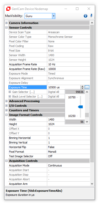
Sample Code in C++
Sample Code in CSharp
Sample Code in VB
Examples
| Visual C++ | VC GenICam Example |
| CSharp | C# GenICam Example |
This GenAPI library contains functions that provide easy control of a GenICam compliant device like a GigE Vision camera.
The CV GenApi Grid Control is available as simple wrapper for the DLL.
For details refer the CVB User Guide for GenICam driver.
Here are listed some practical use cases for the GenICam Library:
Enumeration Access
Software Trigger
Set Exposuretime
Some more can be found in the CVB GenICam User Guide Configuration and SDK chapters.
This Usecase shows how to access enumeration types with the CV GenApi.
As an example we want to read out the display name of the selected pixel format. The PixelFormat feature is normally an enumeration type.
Sample Code in C#
1. Get the pixel format node
2. Get the string of the selected pixel format
3. Get Number of Entries in the pixel format node
4. Find the selected node in the enumeration
5.Release objects which are not needed anymore
Sample Code in C#
Examples
| Visual C# | C# GenICam Example |
If you want to use the iSoftwareTrigger Interface from the GenICam Driver or the iSoftwareTrigger Interface doesn´t work because of a non standard feature Name of the SoftwareTrigger feature you can use the CV GenAPI to generate a software trigger. The condition is that the Camera has a software trigger feature.
To find out which Nodename is used in your camera you can use one of our GenICam examples find the software trigger feature in the CV GenApi Grid Control. With the right mouse button you get into the properties of the feature.
The Name in the Top is the nodename with which you can access this feature. The nodes can be accessed without the namespace "e.g. Cust::". The Type specifies how to access the feature. This is importend for the next step.
There are different ways how the software trigger can be implemented and how to access it. For example:
When the command type is used you can use:
to generate the software trigger.
When the integer type is used you have to generate a rising or falling edge with the integer value. It depends on the configuration of your camera which edge is used. Now we assume you set it to rising edge.
to generate a rising edge and therefore a software trigger you have to set the Integer value from 0 to 1:
To generate another software trigger you have to set the integer value back to 0:
Sample Code in C++
A platform independent C++ code example can be found in the MultiOSConsole Example (Camera.cpp) of the Image Manager
Windows: %CVB%Tutorial\Image Manager\VC\VCMultiOSConsole
Linux: /opt/cvb/tutorial/ImageManager/ComplexMultiOSConsoleExample
The CV Gen API has no seperate function to set the Exposuretime. This is due to the fact that GenICam defines no SetExposuretime function. The camera manufacturer defines the name for the node to access this feature. But the GenICam Standard defines standard feature names which should be used for the Exposuretime:
To find out which Nodename is used in your camera you can use one of ourGenICam examples to find the Exposuretime feature in the CV GenApi Grid Control. With the right mouse button you get into the properties of the feature ( screenshot on the right ). The Name in the Top is the nodename with which you can access this feature. The nodes can be accessed without the namespace "Std::". Read now in our sample codes of your favorite programming language how to set the exposuretime to 20ms. This can be realised with 3 lines of very easy readable code. For the example the standard feature name "ExposureTimeAbs" is used. When your camera has another feature name you have to change it to the available feature name. Other tasks involved might be to check in advance whether the camera possesses a Exposuretime feature and to check whether the new value is consistent with the allowed Exposuretime range.
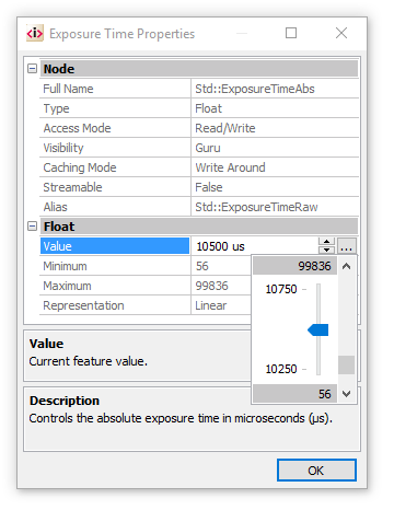
Refer to the Exposuretime sample code example.
CVB Image Manager 3D contains following features for solving 3D tasks:

This type maps directly to an IMG data type with a single plane. Each pixel contains a value which is a function of the height of an object, where the 0 value has the special meaning of unknown height at that point.
Due to the relatively high demands in height most range maps are Mono16 bit images, however other image formats are valid as well. A range map can be generated from a number of different sources, such as 3D cameras. Laser Triangulation is one of the methods available for 3D scanning, where range maps are produced through the accumulation of the shape of laser profiles. Other methods like Time Of Flight cameras, fringe projection or 3D Stereo cameras can also provide range maps, however, the kind of point coordinates stored in those range maps may not be easily related to metric coordinates, and they usually represent the "raw 3D" data acquired.
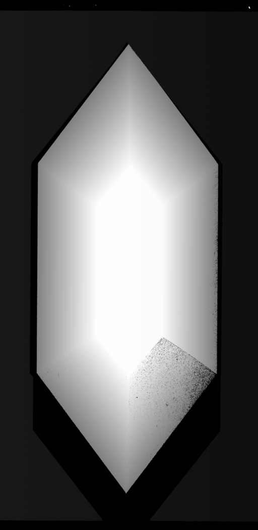
Unlike the range map, the point cloud object (CVCOMPOSITE) stores a set of 3D points (x, y, z and optionally w) in world metric coordinates, describing a point-sampled shape of the surface of a real object. The components' data type can either be float or double. Using proper calibration techniques, range map data can be mapped to metric coordinates to form a cloud of 3D points. This allows 3D metric analysis for the scanned objects. A point cloud can be either unorganized/unordered (sparse) or organized/ordered (dense).
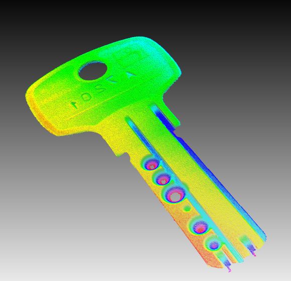
A dense point cloud is an ordered set of 3D points, placed on a grid with a given width and height. The advantage of dense clouds is that you have immediate neighbor information. The disadvantage is, that you cannot have arbitrary clouds (e.g. an affine transformation breaks the lattice view). Also each x-y-position can have only one corresponding z-height. An example are depth images.
Advantages:
Disadvantages:
When to use?
Conversion to sparse?
Each dense point cloud can be converted to a sparse point cloud.
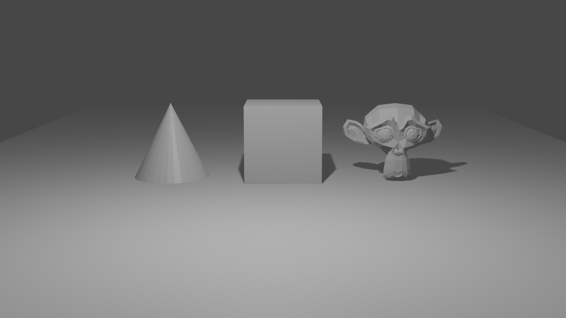
Normal image
Normal image with depth (blue = near, red = far away)
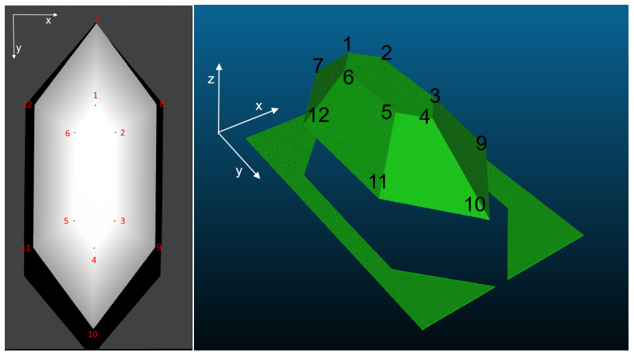
Range image on the left, on the right as dense 3D point cloud
A sparse point cloud is logically seen an array of 3D points. There is no order or neighboring information between the single points. Unlike the dense point cloud it has no grid.
Advantages:
When to use?
Conversion to dense?
Difficult, as you need the grid thus neighbor information.
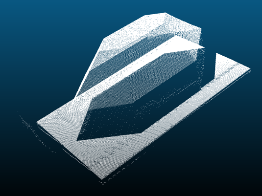
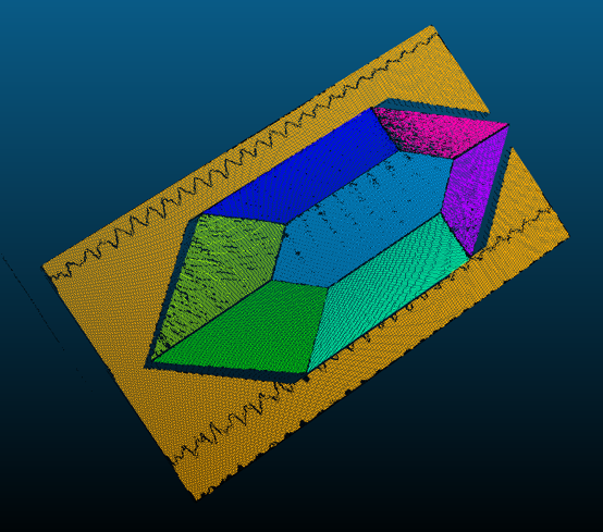
A rectified range map is the result of a planar projection of a point cloud onto the z-plane. As well as the range map a rectified range map maps directly to an IMG data type. However, since it is generated from a point cloud, rectified range maps contain floating numbers. What is the benefit of a rectified range map?
There are a variety of 3D sensors available and many different concepts and output formats. Some output pre-calibrated range maps, where a metric point cloud can be generated by just applying static factors. Others output uncalibrated range maps. Sometimes these uncalibrated range maps come with a set of intrinsic calibration parameters, sometimes it is necessary for users to calibrate a current sensor setup by themselves. The following flow charts demonstrate the principle of CVB handling different input range maps and how to generate desired point clouds:
Case 1 - Convert calibrated range map into point cloud of sensor coordinate system
In this case the sensor outputs pre-calibrated range maps with corresponding static factors for X, Y and Z. The static calibration parameters can be set to a calibrator handle. These factors will be applied to a calibrator handle. The acquired range map and the calibrator will together generate the point cloud. The resulting coordinate system of the point cloud is according to the sensor definitions.
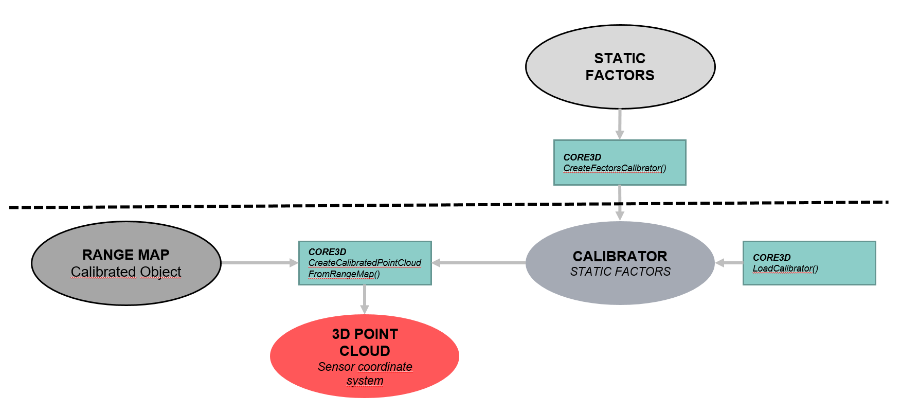
Calibrated range maps may not only have static factors in x,y,z but also static offsets in x,y and z. If this is the case an additional transformation on the 3D point cloud has to be done using function TransformPointCloud() where the rotation matrix is set to identical (not shown in flow chart).
Case 2 - Convert calibrated range map into point cloud of world coordinate system
In this case the sensor outputs pre-calibrated range maps with corresponding static factors. The static calibration parameters can be set to a calibrator handle. In order to transform a resulting point cloud into the desired world coordinate system, the calibrator handle will be updated with extrinsic calibration parameters. These parameters have to be calculated using the Metric function CVMAQS12CalculateCorrectionOfLaserPlaneInclinationFromPiece() or CVMAQS12CalculateRigidBodyTransformationFromPiece() with the AQS12 pattern or on any other way. The acquired range map and the calibrator will together generate the point cloud. The resulting coordinate system of the point cloud is the desired world coordinate system. For detailed information about the calibration with CVB and the AQS12 target see section "Foundation Package -> Foundation API -> Foundation Tools -> Metric".
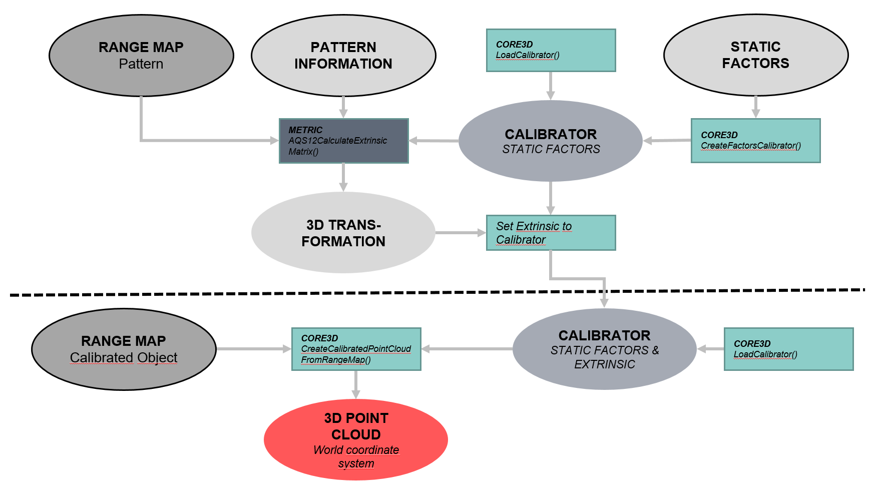
Case 3 - Convert uncalibrated range map with given intrinsic calibration parameters into point cloud of world coordinate system
In this case the sensor outputs uncalibrated range maps, but with corresponding intrinsic calibration parameters The intrinsic calibration parameters can be set to a calibrator handle by loading it from a calibration file. In order to transform a resulting point cloud into the desired world coordinate system, the calibrator handle will be updated with extrinsic calibration parameters. These parameters have to be calculated using the Metric function CVMAQS12CalculateCorrectionOfLaserPlaneInclinationFromPiece() or CVMAQS12CalculateRigidBodyTransformationFromPiece() with the AQS12 pattern or on any other way. CVMAQS12CalculateCorrectionOfLaserPlaneInclinationFromPiece() estimates an affine matrix which is strictly speaking an intrinsic parameter, as the affine matrix corrects errors resulting from an inclined laser plane (laser plane is not exactly vertical to the movement direction) . CVMAQS12CalculateRigidBodyTransformationFromPiece() calculates a rigid-body transformation, which only includes rotation and translation. The acquired range map and the calibrator will together generate the point cloud. The resulting coordinate system of the point cloud is the desired world coordinate system.
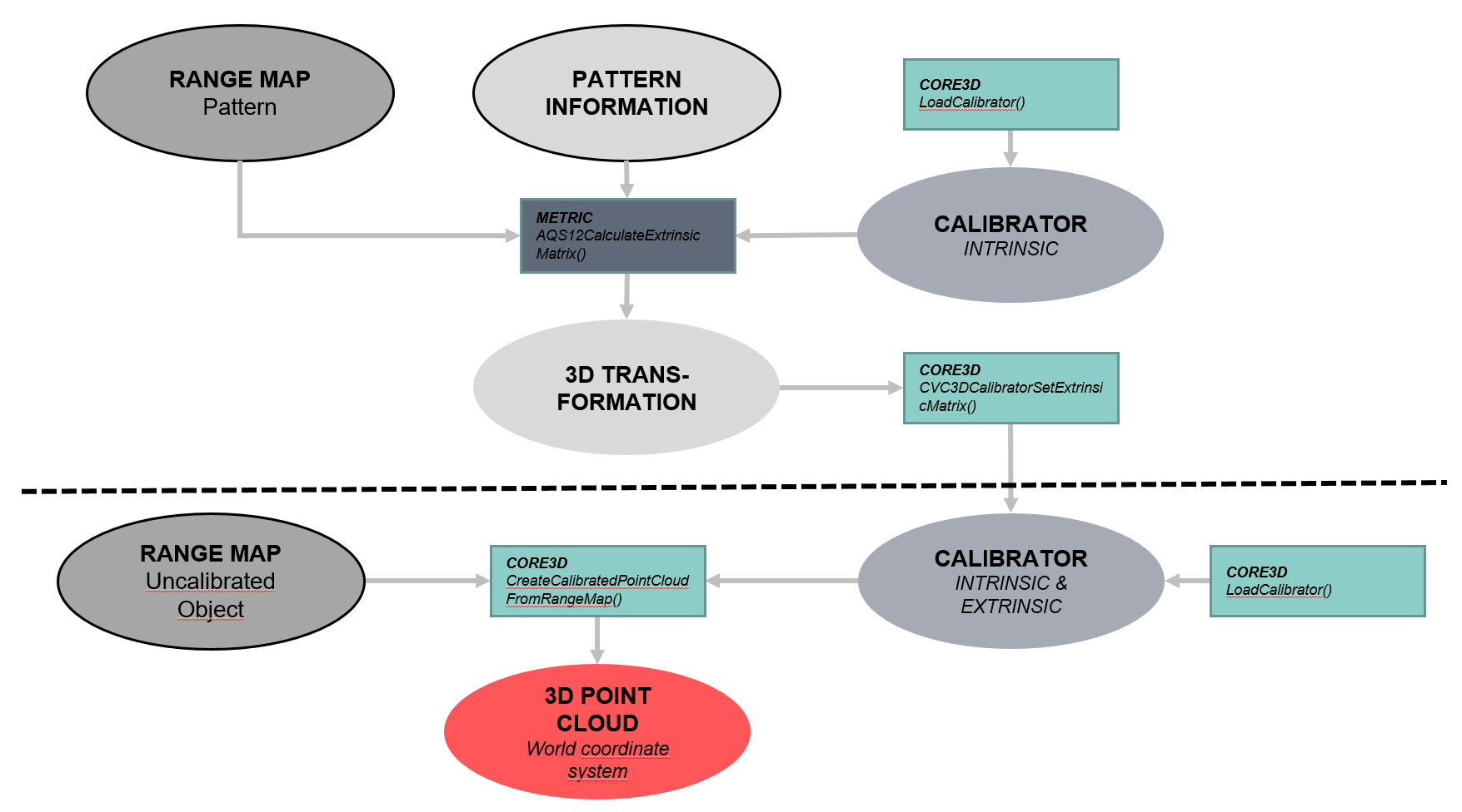
Case 4 - Convert uncalibrated range map into point cloud of world coordinate system
In this case the sensor outputs uncalibrated range maps, with no additional information (e.g. a modular triangulation system). A calibrator handle can be generated using the Metric function CVMAQS12CreateIntrinsicCalibratorFromPiece() or any other way. Both, the intrinsic and extrinsic parameters will be stored in the calibrator handle. The acquired range map and the calibrator will together generate the point cloud. The resulting coordinate system of the point cloud is the desired world coordinate system. For detailed information about the calibration with CVB and the AQS12 target see section Calibration Targets.
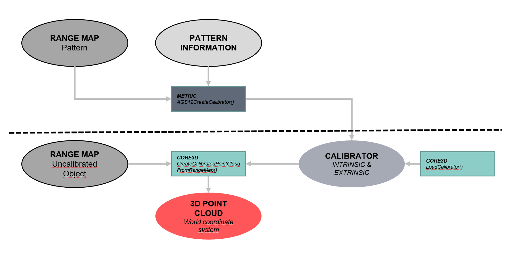
As can be seen in these flow charts the generation of a point cloud always requires a range map and a calibrator object. However, a calibrator can consist of different calibration types.
Create calibrated point cloud with modified sensor settings
One import point to be aware of, is that the calibration parameters stored in the calibrator always refer to the whole sensor (with no mirroring of the pixel coordinates). If the sensor settings of a camera indicate that a sensor region of interest (ROI) is given or pixel coordinates are mirrored, the range map values will be transformed to the sensor coordinates before applying the calibration parameters. In practice especially users of AT cameras have to be careful. In the AT or ZigZag calibration file the default sensor settings are stored. They refer to
If the user acquires a range map with settings that differ from the default ones stored in the calibrator, he may not use the standard function CVC3DCreateCalibratedPointCloudFromRangeMap! Instead he should use function CVC3DCreateCalibratedPointCloudFromRangeMapWithSettings, where he is called upon setting the correct sensor settings. With function CVC3DCalibratorGetSettings the default settings stored in the calibrator can be loaded. CVB release 14.0 supports the following settings, which are described in detail here:
 , where NumSubpixel is the number of subpixels.
In the following table the different settings (1st column) are listed and their notation in the camera properties (2nd column), the AT calibration file (3rd column) and the ZigZag calibration file (4th column). Until now CVB only supports sensor settings of AT cameras.
| CVB parameter | Camera | AT file (xml) | ZigZag file (json) |
|---|---|---|---|
| RangeScale | has to be calculated from Cust::NumSubPixel | intrinsic.rangeScale | 3rd value of intrinsic.factors |
| PixelPosition | Cust::AbsOffsetPos | OffsetTop = 0 | intrinsic.sensorsettings.mode. absolutepositiony |
| PixelsMirrored | std::ReverseX | Width is negative | intrinsic.sensorsettings.mode.reverse.x |
| std::ReverseY | Height is negative | intrinsic.sensorsettings.mode.reverse.y | |
| OffsetLeft | std::OffsetX | intrinsic.sensorRoi | intrinsic.sensorsettings.sensorroi |
| OffsetTop | Cust::AoiOffsetY | ||
| Width | std::Width | ||
| Height | Cust::AoiHeight | ||
| ReductionResolutionHorizontal | not supported yet | intrinsic.rrH | not supported yet |
| ReductionResolutionVertical | not supported yet | intrinsic.rrV | not supported yet |
| EncoderStep | not available | extrinsic.Sy | 2nd value of intrinsic.factors |
CVB supports the following types of point cloud formats:
| Name | Extension |
|---|---|
| Polygon File Format | ply |
| Wavefront OBJ | obj |
| Stereo Lithography | stl |
| TIFF | tif, tiff |
| ASCII | asc, pts, txt, xyz |
| PCD (point cloud library) | pcd |
CVB only works with 3D points and no point relationships like lines, faces, triangles.
With point cloud formats who can handle this information (ply, obj, stl) only the raw 3D points will be read and saved.
As the STL format only supports polygon data, it can't be written in CVB.
Core 3D Library (Enumerations, Events, Methods, Properties)
Core 3D Viewer Control
An example application for creating a point cloud from range map can be found in %CVB%Tutorial\Image Manager\VB.NET\VBCore3D.NET.
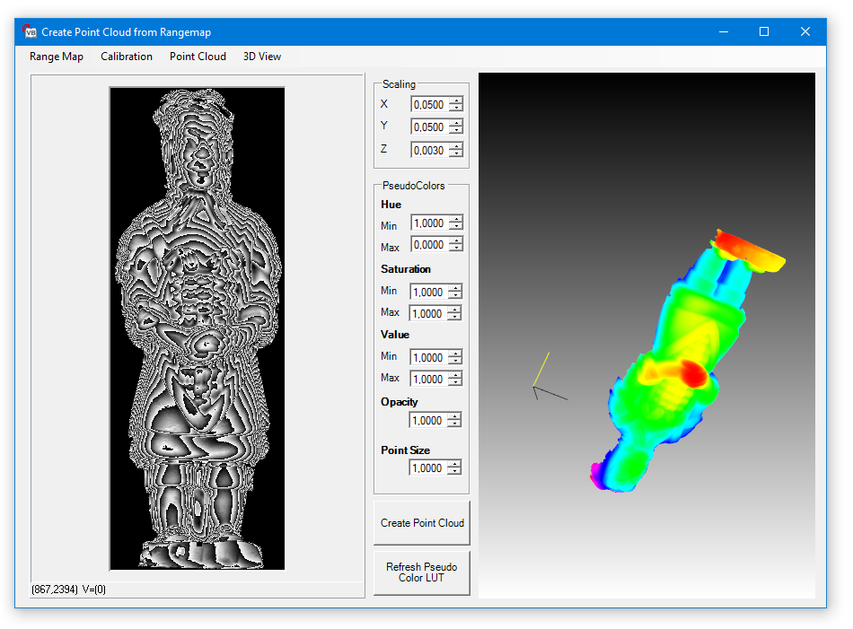
Find Introduction, Enumerations, Events, Methods and Properties for:
The Common Vision Image Control provides a simple way of integrating images in your own applications. When the Common Vision Image Control has been included in the project a CV Image control can be inserted in your own application using the following icon:

The Common Vision Image Control is used for opening and saving image files as well as for checking the image properties. An image file can be addressed using the Filename property or with the LoadImageByDialog and LoadImageByUSerDialog methods. The following image formats are supported:
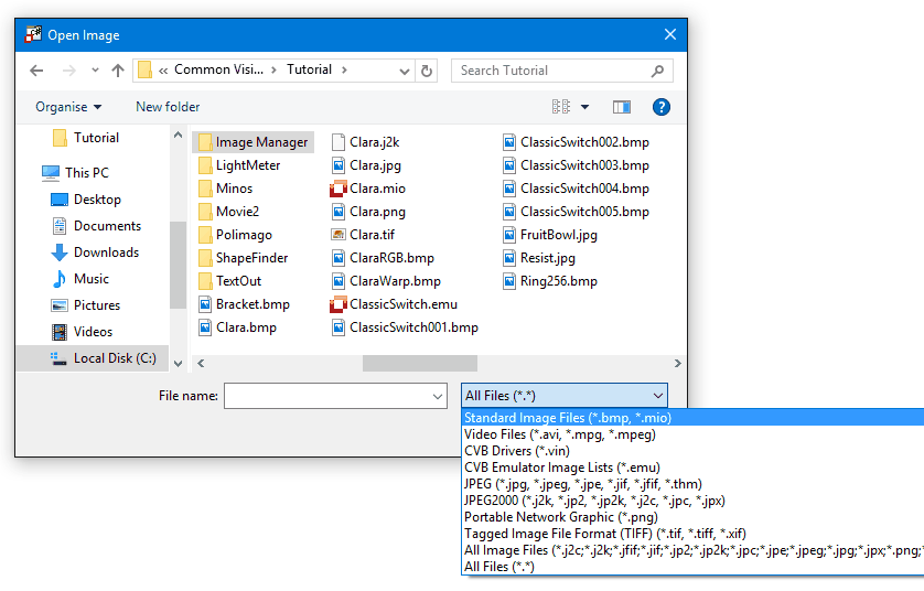
When an attribute has changed, the image is loaded and the image properties, such as its size and dimension, are ascertained. An image can be accessed directly by means of the Image property . The Common Vision Display Control is normally used for display purposes.
The assignment CVDisplay.Image = CVImage.Image displays the image. Filename and Image can be set during development and later at runtime. All remaining properties of the Control are write-protected and serve only to provide the image information.
The SerialNumber property is a special attribute used in querying the serial number of the Common Vision Box protection device. In addition, the Control allows an AOI to be saved and the coordinate system of the image to be changed. This can be done both when the application program is designed and at runtime. The coordinate system can be scaled and rotated independently in the x and y directions.
Another capability of the Image control is to acquire live images. In this process the control uses the CVCDriver and CVCAcq libraries. Live images are acquired in a separate thread. The Control triggers the ImageSnaped event for every new image. Within this event, the image is then processed and the display may be refreshed.
You can set all properties by means of the Properties dialog. You can also make the settings in the Properties window of the Common Vision Image Control .
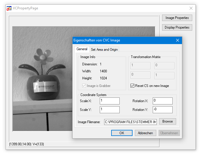
The General tab contains the general options for the Image Control, like determining the Image Filename.
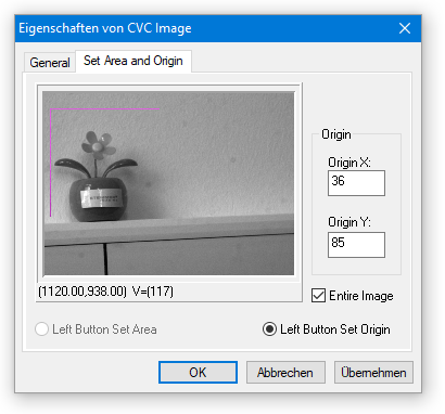
The Set Area and Origin tab contains special options for the Image Control defining the image origin and the Area of interest.
Changes are passed to control by means of the Apply button.
Related Topics
Image file handling (load and save)
File formats
CVdisplay.ocx is based on the Display library.
Introduction
DirectDraw
Labels and Overlay Objects
The Common Vision Display Control is used to display images in a simple and user-friendly way. When the Common Vision Display Control has been included in a project you may add a display window to your own application by means of the following icon:

The Display control supports:
Using the RedPage, GreenPage and BluePage properties you can determine which image plane is to be shown as the red, green or blue page. In this way all the images of a color sequence can be shown in color or each color channel displayed individually as a gray scale image.
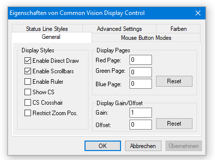
The GENERAL tab contains the general options for the Display settings.
Displaying information in the status bar
In the status bar you can display the gray scale value of the pixel (SL_VALUE) under the cursor position, the location of the cursor (SL_CURPOS), the image size (SL_IMGSIZE), the actual zoom factor (SL_SCALE) and also a user-defined text string. You can control the required condition of the status bar with the Statusline properties (SL_xxx). If no status bar is to be shown, all the SL_xxx properties must be set to FALSE.
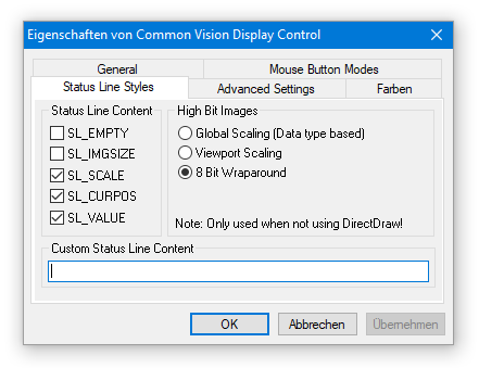
Enable the status bar display of interest by activating the SL_xxx control boxes.
The following functions are controlled by the RightButtonMode property.
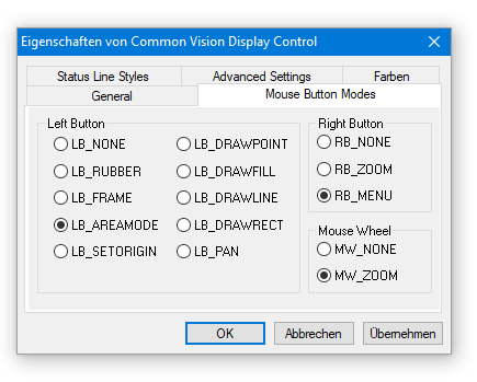
Options of the LeftButtonMode property to define the functionality of the left mouse button.
There are the possibilities to select RB_NONE , RB_ZOOM and RB_MENU. Here a screenshot of the RB_Menu selection.
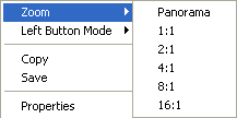
Interactive zooming of images
There are three ways of zooming interactively: Firstly, you can set the zoom factor on a contact menu (RB_MENU) which you open by pressing the right mouse button. Secondly you can zoom directly with the aid of the right mouse button (RB_ZOOM).
In order to magnify the view, hold down the right mouse button in the image section of interest. Release the mouse button when the cursor has become a magnifier. To reduce the view move the cursor to the desired location and press the right mouse button briefly. You can control the function of the right mouse button with the RightButton-Mode property. If the entire image is larger than the display area, use the ShowScrollbars property to get scroll bars which allow you to move to and display all regions of an image.
The third way to zoom the image is to use the mouse wheel. By doing this the zoom factor is increased or decreased, depending on the direction of the wheel. The maximum zoom factor in this mode is higher (64.0) than in the other to modes which supports 16 as the maximum zoom factor. The mode also allows you to zoom the image by values lower than 1.0 and by values other than PANORAMA, 1, 2, 4, 8 or 16. By holding down the 'CTRL' key on the keyboard while using the mouse wheel smaller steps are used.
The following functions are controlled by the LeftButtonMode property.
Drawing rectangles or areas (AOIs)
For the subsequent processing steps you first need to define an area of interest (AOI) in the image. In Common Vision Blox you can define two types of AOIs: a »common« right-angled rectangle and an oblique aligned rectangle, i. e. the coordinate system of the AOI is oriented in an angle. This allows you to process diagonal image areas. The oblique aligned rectangle is described by three points - P0, P1 and P2.
Information on the AOI is displayed in the status bar: When you place the cursor on the border of the rectangle you will see in the status bar the left, top, right and bottom position coordinates (LTRB = Left, Top, Right, Bottom) describing the AOI. An oblique AOI is described through the coordinate origin (circle) and two arrow-heads. When you place the cursor on one of these elements the status bar displays the coordinates of P0, P1 and P2.
More information see in chapter Areas of Interest.
Drawing an AOI
To draw an AOI place the mouse cursor at one of the AOI corners and press the left mouse button. Hold this button down and move the mouse from this corner of the rectangle to the opposite one. If you now release the button you exit the drawing mode. A rectangle is shown on the monitor which marks the edges of the selected AOI. LB_FRAME selects a right-angled AOI and LB_AREAMODE selects an oblique AOI.
Moving an AOI
To move a rectangle, place the mouse cursor approximately in the center of the AOI. In an oblique AOI locate the cursor on the coordinate origin. As soon as the mouse cursor becomes a cross with arrows in four directions press the left mouse button and move the AOI to the new location.
Modifying the size of an AOI
To vary the size of a right-angled AOI place the cursor on one of the edges. In an oblique AOI place the cursor on one of the two arrow-heads. The cursor changes and becomes a double arrow. Now press the left mouse button and hold it down until you have drawn the AOI to the desired size.
Rotating an AOI
You can change the angle of an oblique AOI. Place the mouse cursor on one of the two arrow-heads. The cursor changes and becomes a double arrow. Now press the left mouse button, hold it down and rotate the AOI. When you have reached the angle you wanted exit this mode and release the mouse button.
Deleting an AOI
Click with the left mouse button in the image outside the AOI - the AOI will be removed.
Measuring distances and angles
You can interactively measure distances and angles if the LeftButtonMode property is enabled. To do this, left-click the starting position and hold the button down. Moving the mouse in this mode causes information to be displayed in the status bar. The distance and angle (clockwise, starting at the positive x-axis) related to the starting point are measured and shown.
Altering the coordinate origin of the image interactively
In the property LeftButtonMode LB_SETORIGIN you can alter the coordinate origin of the image. To do this, click on the desired position in the image. If the ShowCS property is set the coordinate origin will be shown either as a crosshair (CoordStyle = CS_CROSSHAIR) or as an angle (CoordStyle = CS_NORMAL).
Drawing interactively in the overlay plane of the image
To change the overlay interactively the LeftButtonMode property can be set to the values LB_DRAWPOINT, LB_DRAWFILL, LB_DRAWLINE or LB_DRAW-RECT. Depending on the chosen parameters you can draw either a point, fill in a closed area, draw a line or a rectangle. The image must be converted into an overlay-capable image beforehand by means of MakeOverlayImage.
Example Tutorial for this is VCSizableDisplay in %CVB%Tutorial\ImageManager\VC directory.
Use right mouse key => Properties over an opened image.
The CVB Image Manager Tutorials VB Display (VBDemo.NET) and VC Display (VC Demo) show the use of the Display Control. Refer %CVB%Tutorial\ImageManager directory.
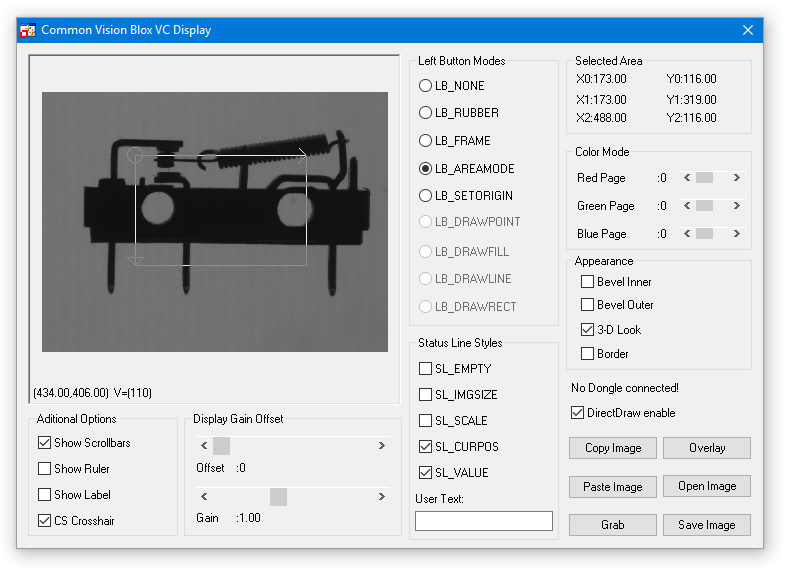
Numerous settings for the image display and handling are made in the Common Vision Display Control.
Common Vision Blox supports DirectDraw. When using DirectDraw the image data is written to offscreen VGA memory, any overlay data is then applied and the image is subsequently copied to the onscreen VGA memory, all of these steps can be handled by the VGA hardware. It is very easy to imagine there could be substantial differences in the drawing speed depending on the graphics hardware being used, a particularly important factor in choosing the VGA card is the size of video RAM. If there is not enough RAM available for both onscreen AND offscreen memory then DirectDraw driver will emulate the hardware functions, if this occurs then the use of DirectDraw may slow the display process down compared with non-DirectDraw display which has been highly optimised in Common Vision Blox.
Another benefit of using the display technique described above is that the overlay is applied to the image data a the refresh rate of the video and not the image data, this creates a flicker free overlay. If DirectDraw is unable to allocate enough memory and emulates hardware functions the overlay is still flicker free.
Common Vision Blox only supports DirectDraw in 16-bit (64K colors) and 32-bit True Color VGA modes. No other VGA color depths are supported. It is important to understand how much the function and speed of DirectDraw depend on the VGA card that is being used as well as the drivers supplied by the VGA card vendor. The AGP based G400 and G450 VGA cards from Matrox and the AGP-based ATI VGA cards have proved to be fast and reliable devices.
If you wish to disable DirectDraw in the system then please refer to the DirectDrawEnabled property of the Display Control for further details.
Related Topics
CanCVBDirectDraw
DirectDrawEnabled
SetGlobalDirectDrawEnabled
GetGlobalDirectDrawEnabled
There are three different types of non-destructive overlays available in the Common Vision Display Control:
Detailed information can be found in the chapter Non-destructive Overlays .
The CV Grabber Control CVGrabber.ocx is based on the Driver library.

The Common Vision Grabber Control provides easy control of an image acquisition device. When the Common Vision Grabber Control has been integrated in a project, a grabber object can be inserted in your own application via the following icon:
The Common Vision Grabber Control is used to control an image acquisition device like a frame grabber or a camera. It incorporates, for example, functions to change the camera port and to set the trigger mode. Like all other Common Vision Blox Controls, the Common Vision Grabber control has an Image property which lets a Common Vision Blox-compatible image to be passed to the Control .
Note that the image must originate from a driver. With the aid of the Common Vision Grabber Control it is possible to ascertain which interface is provided by the image. The CanXXX properties make it possible to check whether the image provides an interface or not. Before the camera port is changed, for instance, an application should check whether the ICameraSelect interface is available.
In the supported compilers you can set all properties by means of the Properties dialog. You can also make the settings in the Properties window of the Common Vision Grabber Control.
The first tab of the dialog named General shows the available interfaces for the the assigned image source:
In the next tab named SelectCamera you can access ICameraSelect and ICameraSelect2 properties and methods. To refresh the settings click the Refresh button:
In tab SelectBoard you can access IBoardSelect and IBoardSelectSelect2 properties and methods. To refresh the settings click the Refresh button:
In tab Trigger you can access ITrigger and ISoftwareTrigger properties and methods, ensure proper configuration file settings for your image acquisition device before using the functions:
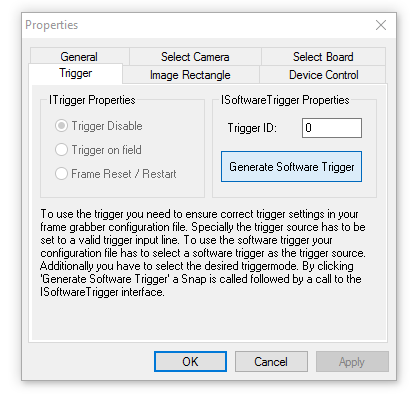
In tab ImageRectangle you can access IImageRect properties and methods. If you specify invalid settings for offset and size a dashed red rectangle will appear indicating the maximum size to specify:
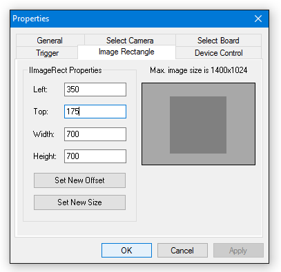
In tab DeviceControl you can access IDeviceControl properties and methods. Notice that only string commands are supported on this page. The parameters for the DeviceControl Operation are explained with the SendStringCommandEx method. Refer to the CVB Driver User Guide of the specific image acquisition device for valid commands and their parameters:
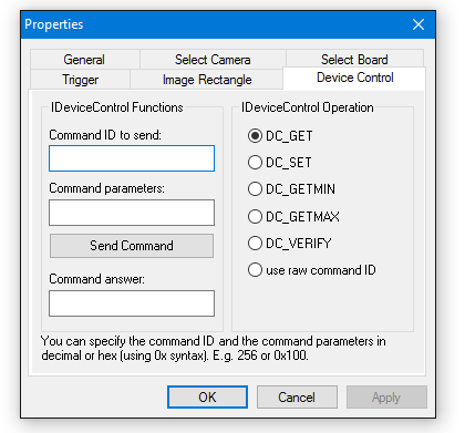
Changes are passed to control by means of the Apply button.
Related Topics
Framegrabber and Camera Driver
The CV DigIO Control CVDigIO.ocx is based on the Driver library.

Introduction
Inverting the state of a port for a specific time
Monitoring a port or group of ports
Reading and writing individual ports or port groups
The DigIO control is designed to offer a device independant interface to digital I/O ports (or channels) on image acquisition devices.
The CVB BasicDigIO interface supports reading and writing of individual ports, reading and writing of groups of ports, monitoring ports for changes in state and also for creating output pulses of defined widths. The CVB BasicDIGIO interface is accessed via the Common Vision Digital IO control or the CVCDriver DLL.
This document describes the CVB BasicDigIO interface capabilities and provides detailed information on the properties, methods and events associated with it.
Reading and writing individual ports or port groups
Monitoring a port or a port group
Inverting the state of a port for a specific time
Visual development environments allow control properties to be configured by means of the Properties dialog. The general properties of the CVB DigIO control, such as the number of ports, can be viewed on the General tabbed page (refer CVB Viewer).
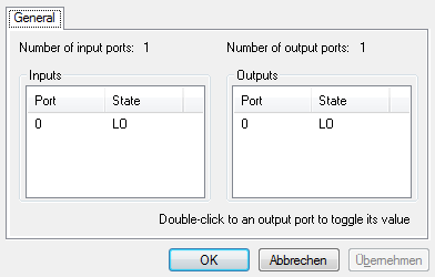
The states of the ports are shown online and the output port state can be switched by double-clicking the port in question.
Related Topics
IBasicDigIO Functions in the CVCDriver.dll
Examples
| Visual C++ | VC Digital I/O Example |
The Toggle functions in the CVB DigIO control allow the state of a port to be inverted for a specific period of time.
If for example a port is LOW when the BitTogglerStart method is called it is immediately set HIGH, after the specified period of time the port is reset LOW again,
the opposite would happen if the port were HIGH when BitTogglerStart was called. This operation if performed in a background thread, i.e. the BitToggleStart returns control immediately and not when the specified time has elapsed, this allows the controlling application to continue processing. The Toggler event if fired when the port is reset to its initial state.
Pulses of programmable length can be generated in this way for a number of purpose including :
The Listener functions in the CVB DigIO control allow a port or group of ports to be monitored for a specific state, if this state is achieved then the Listener event is fired.
Monitoring itself takes place in a background thread while the application is running in parallel to it. Any number of monitoring threads can be generated and started although the response time of the monitoring threads depends on the system workload, for this reason the number of monitoring threads started should be kept to a minimum.
NOTE
The CVB DigIO control uses the same multithreading methods as the CVB Image control. This means that the threads are controlled via the SetGlobalAsyncACQEnabled function , please refer to the "Multithreading" section in the CVB Image Control documentation for further information.
Image acquisition devices generally have a number of digital input and output ports (typically 8 of each), the number of supported inputs and outputs can be returned by the CVB DigIO control. Each of the ports has two states: LO (value 0) and HI (value 1) and the control allows the ports to be controlled individually or in groups.
To control a group of ports, logical operations are applied to the bit values of each individual port in the group. Up to 32 ports can be combined in a group and this can then be actuated in a single operation. The number of port groups is calculated using the following formula:
Ngroups = Nports / 32 + 1
If a device has 8 ports, then they can be combined as 8 / 32 + 1 = 1 group. If, for example port 1 and 4 have to be set HI (value 1) and port 0 has to be set LO then the following applies :
| Not Port 0: | 00000 |
| Port 1: | 00010 |
| Port 4: | 10000 |
| Port 0 or port 1 or port 4: | 10010 = 18 |
To prevent port 2 and 3 being overwritten by the new value in our example, a mask is used, this mask describes which bits are to be written.
The following would be the mask in our example:
| Port 0: | 00001 |
| Port 1: | 00010 |
| Port 4: | 10000 |
| Port 0 or port 1 or port 4: | 10011 = 19 |
An individual input port can be read in the CVB DigIO control with the GetInBit method, the state of the output port can be read with GetOutBit and be written with SetOutBit. A port group can be accessed in an equivalent way with GetInDWORD, GetOutDWORD and SetOutDWORD.
The CV RingBuffer Control CVRingbuffer.ocx is based on the Driver library.

The Common Vision RingBuffer Control provides easy control of image acquisition devices ringbuffer used to acquire images. When the Common Vision RingBuffer Control has been integrated in a project, a RingBuffer object can be inserted in your own application via the following icon:
The Common Vision RingBuffer Control is used to control the ringbuffer of an image acquisition device that is used to acquire images. Not all frame grabbers support this features so you should use the CanRingBuffer property of the CV Grabber control to verify if this interface is provided by the driver being used. As it is common to all Common Vision Blox controls the image is passed through the Image property of the control. The acquisition into the ringbuffer is started by setting the Grab property of the CV Image control to TRUE. It is important to know that it is not allowed to change any of the properties of the control while a Grab is active. Each buffer of the ringbuffer can individually be write protected so that the control can be used to record a high speed sequence into memory without any CPU load. You might also use the control to store error images to disk when the system is idle or to process images delayed when the system is temporarily busy.
You can set all properties by means of the Properties dialog. Settings can also be made in the Properties window of the Common Vision RingBuffer Control. To do so a supported image (including the IRingBuffer interface) has to applied to the Control .
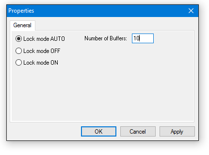
Related Topics
IRingBuffer Interface
IGrab2 Interface
The CV GenApi Grid Control CVGenApiGrid.ocx is based on the GenICam library.

The Common Vision GenApi Grid Control provides easy control of a GenICam compliant Camera.
For Example it is possible to change the ExposureTime with typing in a value or using the slider. Or if the camera vendor provides it you can save user settings into the camera. With the right mouse button you get into the properties of every feature (screenshot above).
In this page you can see the properties of one feature. For example you can see the Minimum and Maximum values.
Getting a NodeMap from a GenICam™ compliant Camera to the GenApi Grid Control
If you want to use the GenApi Grid you have to give the Grid access to a NodeMap from a GenICam™ compliant Camera. First you can check if the loaded vin-Driver can get a NodeMap with CanNodeMapHandle. After that you can get the NodeMap from the Camera with NMHGetNodeMap. Now you can set the NodeMap to the Grid with the NodeMap property.
Get the NodeName of the Feature
To access features from the NodeMap you need the name of the node. You can get the name of the node when you open an application like the CVB GenICam Browser which uses the CV GenApi Grid Control. With this you can find the feature and read out the name from the description area on the bottom part of the Grid Control. E.g. Std::ExposureTimeAbs for the Exposure Time.
You can double click on the feature name and the name except the namespace (Std::) is marked. Then you can copy it to the clipboard and the paste it to your code.
The namespace is not needed to access features with the CV Gen API. Only if features exists with the same name in different namespaces. Then you have to access the feature with the namespace. Otherwise the standard feature (Std::) is preferred against a custom feature (Cust::).
Sample Code in C#
Sample Code in C++
Examples
| Visual C++ | VC GenICam Example |
| CSharp | C# GenICam Example |
The CVCore3D Viewer Control CVCore3DViewer.ocx is based on the Core3D library.
There is a vast range of so-called Tutorials (sample programs) available in source code and as executables which are based on the Image Manager Libraries and Controls.

| Visual C++ Examples |
| .Net Examples |
More sample programs can be found in %CVB%Tutorial\ directory.
VC Bitmap Overlay Example
VC Digital I/O Example
VC Display Example
VC Driver MDI Interfaces Example
VC Histogram Example
VC Image Normalization Example
VC Image Overlay Example
VC Image Statistics Example
VC Linear Image Access Example
VC Overlay PlugIn Example
VC Pixel Access Example
VC Property Pages Display Example
VC Right Mouse Button Example
VC RingBuffer Example
VC Rotation 90 degree Example
VC Sizeable Display Example
VC Static TextOut OverlayPlugIn Example
VC VPAT Example
VC Warping Example
Aim
The Common Vision Blox VC Bitmap Overlay example demonstrates how to use the bitmap overlay plugin.
Instructions
Load a stored image or image acquisition device (*.vin) with the 'Open Image' button, the picture will then be displayed and certain areas with a greyvalue below the selected threshold will appear green.
The example creates a bitmap with the same dimensions as the source image, this bitmap is then passed to the bitmap overlay plugin to be displayed. The example processes the entire source image and for every pixel below a specified threshold, the corresponding bitmap pixel is set, if the pixel is above the threshold specified the bitmap pixel is transparent.
Location
Startmenu: Common Vision Blox -> Image Manager-> Visual C++ -> VC Bitmap Overlay Example
Path: %CVB%Tutorial\Image Manager\VC\VCBitmapOverlay
Functions Used
LoadImageByDialog,
SaveImageByDialog,
Bitmap OPI,
AddOverlayObject,
RemoveOverlayObject,
GetIsGrabber,
IsImage,
GetImage / SetImage,
SetGrab,
Refresh,
GetLinearAccess
Aim
The aim of the Common Vision Blox Digital I/O examples is to show how the I/O ports of an image acquisition device like a frame grabber or a camera can be controlled using Common Vision Blox.
Instructions
To control the I/O ports of a image acquisition device, a vin- driver that supports the DigIO interface has to be loaded. This is done by selecting the 'Open Image' button and loading a VIN file. With an image acquisition device driver loaded that supports the DigIO interface the 'IO Properties', 'Listen to port #0' and 'Toggle port #0' buttons become active. The 'IO Properties' button displays the property page of the Digital I/O Control.
The 'Listen to port #0' button creates a listener object, this object checks the state of port 0 and 'Listener Event' is fired after port has changed state, a message box is displayed in this event.
The 'Toggle port #0' button changes the state of the ouput port number 0.
Location
Startmenu: Common Vision Blox -> Image Manager-> Visual C++ -> VC Digital IO Example
Path: %CVB%Tutorial\Image Manager\VC\VCDigIO
Functions Used
GetIsBasicDigIO,
BitListenerCreate,
BitListenerStart,
BitListenerStop,
BitListnerDestroy,
BitTogglerCreate,
BitTogglerStart,
BitTogglerDestroy,
ShowPropertyFrame,
SetGrab
Aim
The aim of the Common Vision Blox Display examples is to show loading, saving and display of either stored images or live images from an image acquisition device like a frame grabber or a camera .
The examples also demonstrate the Common Vision Blox Display Control properties and their control at run time.
Instructions
To display stored images, open a file by clicking on 'Open Image' and selecting 'Open', sample images are stored in the 'Common Vision Blox\Tutorial' directory. To display live images from an image acquisition device the appropriate driver for the installed device has to be selected, this is done by clicking 'Open Image', changing the file type to 'Driver's (*.vin)', and then selecting the correct driver. Drivers are normally located in 'Common Vision Blox\Drivers' directory.
The 'Grab' button is only activated when the image source is an image acquisition device like a frame grabber or a camera.
While displaying images, different properties of the Common Vision Blox Display Control can be altered.
For further information see 'Common Vision Blox Display Control'.
By using the 'Save', 'Copy' and 'Paste' buttons images can be saved, copied into the clipboard, or copied from the clipboard into the current display.
Location
Startmenu: Common Vision Blox -> Image Manager-> Visual C++ -> VC Display Example
Path: %CVB%Tutorial\Image Manager\VC\VCDemo
Functions Used
LoadImageByDialog,
SaveImageByDialog,
CopyImageToClipboard,
PasteImageFromClipboard,
MakeOverlayImage,
GetSelectedArea,
SerialNumber,
SetDisplayGain,
SetDisplayOffset,
SetRedPage,
SetGreenPage,
SetBluePage,
Grab,
AddLabel,
RemoveLabel
Aim
The Common Vision Blox VC MDI Driver Interfaces Example demonstrates how to use the different driver interfaces using DLL functions in VC++. The Example allows live acquisition and display of multiple image acquisition devices like cameras or frame grabbers.
Instructions
The common dialogs are added to the application so any image source ( *.bmp, *.vin, *.avi ...) can be loaded, saved, copied to the clipboard, pasted from the clipboard or printed. For images coming from an image acquisition device ( *.vin drivers) live images are displayed ( Grab2 grab , Ping Pong grab, grab) and there is a property page named 'Image Properties' which can be opened to access the different driver interfaces.
Image acquisition is done in separate threads using either the IGrabber, IPingPong or IGrab2 interface.
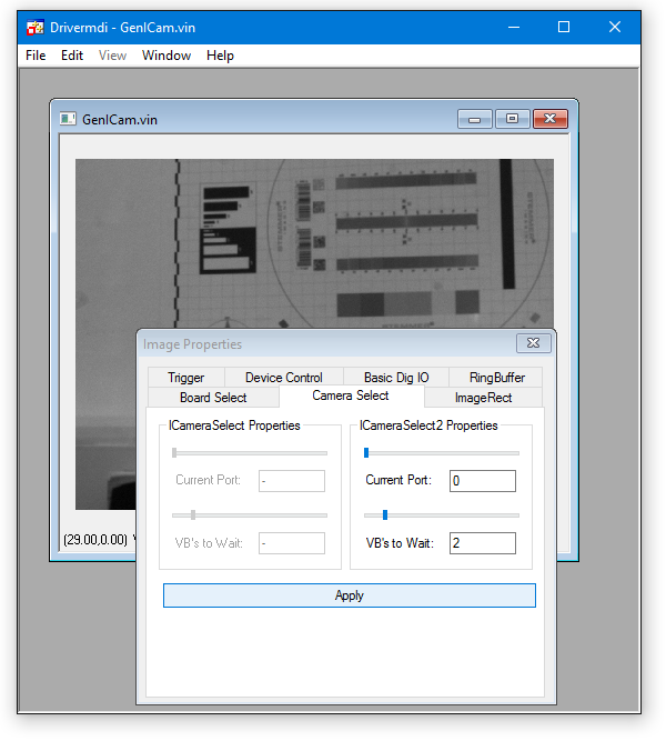
Location
Startmenu: Common Vision Blox -> Image Manager-> Visual C++ -> VC Driver MDI Example (DLL only)
Path: %CVB%Tutorial\Image Manager\VC\VCPureDLL\VCDriverMDI
Functions Used
LoadImageByDialog,
CopyImageToClipboard,
PasteImageFromClipboard,
SetImage / GetImage,
SetFilename
and more or less all functions of the CVCDriver DLL.
Aim
The Common Vision Blox VC GenICam example shows, how to use the CV GenICam Library and the CV GenApi Grid Control.
Instructions
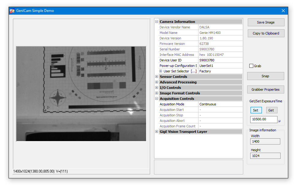
The GenICam vin-driver has to be loaded manually with the "Load Image" button.
If there is a GigE camera connected to the PC and configured in the GenICam.ini file then the GenApi Grid Control loads the NodeMap from the camera to show all available features. In the Set/Get Exposuretime Area the exposuretime is read out from the camera if available. Then you can set the exposuretime in this area. The image dimensions in the Image information area are read out by the CV GenICam Library. This are mandatory features which means that they are available on every GenICam compliant camera. The Exposuretime instead is not a mandatory feature. Because of this the nodenames for the exposuretime from the camera can also be different. And then it is possible that you can´t set or get the exposurtime because this example uses the recommended nodenames for the exposuretime feature.
Location
Startmenu: Common Vision Blox -> Hardware -> GenICam -> VC++ SimpleDemo
Path: %CVB%Tutorial\Hardware\GenICam\VC\VCSimpleDemo
Functions Used
NMGetNode,
NInfoAsInteger,
NGetAsString,
NSetAsString
Aim
The aim of this example is to demonstrate how to create and display a histogram of an image. The histogram can be created from the full image or a region of interest.
Instructions
After displaying a live image or stored bitmap, a histogram of the image image will appear in the lower display window. A region of interest can be drawn with the mouse, only this selected area is used to calculate the histogram. The position and size of the AOI can be changed by using the mouse, the histogram is automatically adjusted.
The slider sets the scanning density for the histogram calculation.
Location
Startmenu: Common Vision Blox -> Image Manager-> Visual C++ -> VC Histogram Example
Path: %CVB%Tutorial\Image Manager\VC\VCHisto
Functions Used
LoadImageByDialog,
GetIsGrabber,
SetImage / GetImage,
GetGrab / SetGrab,
SetArea,
Refresh,
GetSelectedArea,
ImageHistogram
Aim
The Common Vision Blox VC Image Normalisation example shows, how to normalise image data by using Common Vision Blox.
Instructions
Load a stored image or live image with the 'Open Image' button, the normalized image appears in the right hand window. It is possible to choose between two different methods to normalise the image.
The first is 'Mean-Variance Mode', you can set the mean of the histogram with the upper slider and the variance with the lower slider. The second method is 'Min-Max Mode', the minimum value is regulated by the upper slider and the maximum value is regulated with the lower slider. For both of the mode the contents of the right window is adjusted immediately.
As an example load an image acquisition device (*.vin) and select 'Mean-Variance Mode'. Set the 'Mean' value to 128 and the 'Variance' value to 64, enable live image display and change the aperture of your camera. While the original image changes, the resulting image stays constant over a wide range.
Location
Startmenu: Common Vision Blox -> Image Manager-> Visual C++ -> VC Image Normalization Example
Path: %CVB%Tutorial\Image Manager\VC\VCNormalize
Functions Used
LoadImageByDialog,
GetIsGrabber,
SetImage / GetImage,
SetGrab,
Refresh,
CreateNormalizedImage,
ReleaseImage
Aim
The Common Vision Blox VC Overlay example demonstates how to create UserOverlay objects.
Instructions
Load a stored image or a live image from an image acquisition device like a frame grabber or a camera with the 'Open Image' button. A triangle, ellipse or line can be created on the display by using the respective buttons.
If the 'Dragable' checkbox is activated, the size and position of the overlay can be changed with the mouse. If the 'XOR-Only' checkbox is selected, the overlay is the exclusive-or of the background and the overlay data, if this checkbox is not selected the overlay is solid colour. The status line displays the position of the vertices of the overlay or the center of gravity, using the mouse it is possible to 'Pickup' these points.
Location
Startmenu: Common Vision Blox -> Image Manager-> Visual C++ -> VC Overlay Example
Path: %CVB%Tutorial\Image Manager\VC\VCOverlay
Functions Used
LoadImageByDialog,
GetIsGrabber,
SetImage / GetImage,
SetGrab,
GetImageWidth,
GetImageHeight,
Refresh,
AddUserObject,
RemoveUserObject,
RemoveAllUserObjects
Aim
The Common Vision Blox (CVB) VC Image Statistics example demonstrates the concept of the 'Common Image Model' that a CVB Image is based on. An image can have any number of dimensions, or planes, a multidimensional image is regarded as a vertical stack of one-dimensional images. This example shows how statistical information can be build up from an image stack with any number of planes.
Instructions
Load a stored image or an image acquisition device driver (*.vin) with the 'Open Image' button, this will be displayed in the upper left window. Pressing the 'Concat' button will cause images to be displayed in the other windows. If a monochrome image is selected or you are displaying a monochrome image from a frame grabber or camera, the same image appears in all other windows except the bottom right.
Now open a second monochrome image or snap another image and click the 'Concat' button, all the displayed images will be changed. The 'Concat' button creates a new image that is one plane deeper than the current image, the 'Single Image' is added to this extra plane. In the 'Multi Dimension Image' display you can switch between all the planes in the image using the slider.
The maximum intensity image of all planes is displayed in the 'Max Image' frame and the minimum intensity image in the 'Min Image' frame. The planes are averaged in the 'Mean Image' frame and the 'Variance Image' frame contains the variance image of the different planes.
When displaying a colour image the 'Concat' button will cause different images to be displayed in the different windows, this occurs because a color image consists of multiple planes.
For further information please see 'Proposal for a Common Image Model' in the Common Vision Blox documentation.
Location
Startmenu: Common Vision Blox -> Image Manager-> Visual C++ -> VC Image Statistics Example
Path: %CVB%Tutorial\Image Manager\VC\VCMultiDim
Functions Used
LoadImageByDialog,
SaveImageByDialog,
GetIsGrabber,
SetImage / GetImage,
SetGrab,
GetDisplayZoom,
SetDisplayZoom,
SetRedPage,
SetGreenPage,
SetBluePage,
CreateImageInsertList,
CreateImageDeleteList,
CreateGenericImage,
CreateMeanVarianceImage,
CreateDuplicateImage,
CreateMinMaxImage,
MaxImageArea,
InitializeImageArea,
ReleaseImag
Aim
This example demonstrates analysis of the VPAT, and direct access to image data using a simple pointer. This example could be extended for users who want to transfer existing algorithms to become 'Common Vision Blox Compliant'.
Instructions
Load an image file with the 'Open Image' button and click on 'Analyse X-VPAT' or 'Analyse Y-VPAT'. The application will display information about the orientation of the image data in memory.
The 'Linear Access' button overwrites the current image data with a greyscale wedge, this function could be extended to support a custom algorithm.
Location
Startmenu: Common Vision Blox -> Image Manager-> Visual C++ -> VC Linear Image Access Example
Path: %CVB%Tutorial\Image Manager\VC\VCAnalyseVPAT
Functions Used
LoadImageByDialog,
SaveImageByDialog,
GetIsGrabber,
IsImage,
SetImage / GetImage,
GetGrab / SetGrab,
SetArea,
Refresh,
GetSelectedArea,
AnalyseXVPAT,
AnalyseYVPAT,
GetLinearAccess
Aim
The Common Vision Blox VC MDI example demonstrates how to create a 'Multiple Document Interface' application.
Instructions
The creation of a Common Vision Blox MDI application is described in detail in the chapter How to create a Visual C++ Application with Common Vision Blox .
The common dialogs are added to the application so an image can be loaded, saved, copied to the clipboard, pasted from the clipboard or printed.
Functions Used
LoadImageByDialog,
CopyImageToClipboard,
PasteImageFromClipboard,
SetImage / GetImage,
SetFilename
Aim
The Common Vision Blox VC Overlay PlugIn example demonstrates how to use overlay PlugIn's.
Instructions
Load a stored image or image acquisition device with the 'Open' button.
All the available plugin's are displayed in the listbox, double clicking on these plugins will create them on the current display.
If the 'XOR only' checkbox is selected, the overlay is the exclusive-or of the background and the overlay data, if this checkbox is not selected the overlay is solid colour. If the 'Filled' checkbox is selected and the plugin supports filled mode then it will be created accordingly. The 'Dragable' checkbox defines whether the user can manually move the plugin.
The status line displays the position of the vertices of the plugin or the center of gravity, using the mouse it is possible to 'Pickup' these points.
Location
Startmenu: Common Vision Blox -> Image Manager-> Visual C++ -> VC Overlay PlugIn Example
Path: %CVB%Tutorial\Image Manager\VC\VCOverlayObjects
Functions Used
LoadImageByDialog,
SaveImageByDialog,
IsOverlayObjectAvailable,
AddOverlayObject,
HighLightOverlayObject,
GetOverlayObjectPosition,
MoveOverlayObject,
RemoveOverlayObject,
RemoveAllOverlayObjects,
GetAOOCount,
SetAOOIndex,
GetAOOName,
AddPixel,
CreatePixelList,
Overlay PlugIn PixelList,
GetIsGrabber,
IsImage,
GetGrab / SetGrab,
Refres
Aim
This example demonstrates access to image data using both Scan functions and the Virtual Pixel Access Table (VPAT).
Instructions
Load an image and select 'VPA Access', every second row of the image will be inverted by accessing data through the VPAT.
An alternative method of accessing data is the 'Scan Functions'. These functions allow sub sampling by setting the 'Density' value between 0 and 1000. It is also possible for the co-ordinate system to be enabled or disabled when using 'Scan Functions'. The origin of the coordinate system can be moved by using both check boxes.
As an example of the co-ordinate system, move the origin, enable 'Use Coordinate System' and select 'R/W Line', the line will now be written at a different position.
Location
Startmenu: Common Vision Blox -> Image Manager-> Visual C++ -> VC Pixel Access Example
Path: %CVB%Tutorial\Image Manager\VC\VCAccess
Functions Used
LoadImageByDialog,
SetImage / GetImage,
ImageWidth,
ImageHeight,
GetImageDimension,
AddLabel,
RemoveAllLabels,
GetSelectedArea,
SetArea,
GetImageVPA,
GetImageOrigin,
ScanPlaneUnary
Aim
The aim of the Common Vision Blox (CVB) Property Page examples is to show how the CVB Image Control and CVB Display Control property dialogs can be displayed and modified at run time.
Instructions A stored image or image acquisition device can be loaded using 'Browse' button in the 'Image Properties'. General properties like the coordinate system scaling and rotation, and the transformation matrix of the image can be set in the 'General' tab. In the 'Set Area and Origin' tab the origin of the co-ordinate system can be set.
After selecting the 'Display Properties', general display control settings can be made in the 'General' tab. The functionality of the mouse buttons can be set in the 'Mouse Button Modes' tab, and finally the desired status line properties can be selected in the 'Status Line Styles' tab.
Location
Startmenu: Common Vision Blox -> Image Manager-> Visual C++ -> VC Property Pages Example
Path: %CVB%Tutorial\Image Manager\VC\VCPropertyPage
Functions Used
ShowPropertyFrame,
SetImage / GetImage
Aim
The aim of the Common Vision Blox RingBuffer example is to show how to use the Common Vision RingBuffer control together with the IGrab2 interface functions provided with the acquisition functions of the Common Vision Image control.
Instructions
To control the acquisition ringbuffer of an image acquisition device like a frame grabber or a camera you have to load a driver which supports the IGrab2 and IRingBuffer interfaces. Refer to the CVB Driver User Guide of the specific image acquisition device to verify if it supports these interfaces.
The VCRingBuffer example lets you set the lockmode for the buffers in the ringbuffer. If you load a driver and select the LM_AUTO option the buffers have to be unlocked manually. After starting a grab the buffers will fill as images are acquired from the camera. The buffers are locked but not unlocked automatically meaning that no images will be acquired after the ringbuffer was filled with images. The acquisition stops but as soon as you unlock one of the buffers a new image will be acquired immediately. You can unlock a single buffer by click the corresponding Unlock button. Try different lockmodes to study the different lockmode behaviours.
Location
Startmenu: Common Vision Blox -> Image Manager-> Visual C++ -> VC RingBuffer Example
Path: %CVB%Tutorial\Image Manager\VC\VCRingBuffer
Functions Used
Image,
CanGrab2,
CanRingBuffer,
GetGrab2Status,
NumBuffers,
Unlock,
LockMode,
IsLocked,
GetBufferImage
Aim
The aim of the Common Vision Blox Right Mouse Button examples is to demonstrate the flexibility of the right mouse button and show how the properties can be changed at run time.
Instructions
Load an image with the 'Open' button, the function of the right mouse button can then be changed.
Location
Startmenu: Common Vision Blox -> Image Manager-> Visual C++ -> VC Right Mouse Button Example
Path: %CVB%Tutorial\Image Manager\VC\VCRightButton
Functions Used
LoadImageByDialog,
IsImage, GetImage / SetImage,
GetIsGrabber,
SetGrab,
GetRightButtonMode / SetRightButtonMode,
SetStatusScale / GetStatusScale,
SetStatusGrayValue / GetStatusGrayValue,
SetStatusImageSize / GetStatusImageSize
Aim
The main feature of this example is to show the fast access to LIVE image data via the CVB virtual pixel access table (VPAT).
A possible area of application is, if the position of your camera has changed and therefore your view has changed, too.
Instructions
Load a bitmap or open a driver (*.vin) for your image acquisition device to get an image. The "Grab" check box offers you to acquire live images via your device.
Location
Startmenu: Common Vision Blox -> Image Manager-> Visual C++ -> VC VPAT Rotation Example
Path: %CVB%Tutorial\Image Manager\VC\VCRot90
Functions Used
CreateImageMap
GetImageVPA,
LoadImageByDialog,
SaveImageByDialog,
ImageWidth,
ImageHeight,
RemoveOverlayObject,
IsGrabber,
IsImage,
Image,
Grab,
Image Snaped,
Refresh
Aim
The example shows you the use of the StaticTextOut Overlay PlugIn which offers you the possibility to draw user defined text in the display overlay.
Instructions
Load a bitmap or open a driver (*.vin) for your image acquisition device to get an image. With the "Grab" check box you could acquire live images via your device.
Clicking on the button "Add StaticTextOut" the user defineable text in the edit box will be displayed at a given position. The function inserts a defined string as non-destructive text-overlay to the display. The given position of the text is represented with a marker (red cross) or without a marker, depending on the status of the Marker-check box. For a better overview the colour of the text overlay is selectable.The button "Remove All" removes all text overlays. If you place the cursor at the top left corner or at the marker of the overlay you are able to move the text in the display.
Location
Startmenu: Common Vision Blox -> Image Manager-> Visual C++ -> VC Text Overlay PlugIn Example
Path: %CVB%Tutorial\Image Manager\VC\VCStaticTextOut
Functions Used
LoadImageByDialog,
SaveImageByDialog,
AddOverlayObject,
Static Text Out OPI,
RemoveAllOverlayObjects,
IsGrabber,
IsImage,
Image,
Grab,
Image Snaped,
Refresh
Aim
The Common Vision Blox (CVB) VC Sizeable Display example demonstrates a CVB display dynamically adjusted in size to the size of the window.
Instructions
Load an image or image acquisition driver ( *.vin) or any other image source using the 'Load Image' button, then resize the window and the display size is adjusted dynamically. A right mouse click give you the menu of the CV display which allows changing zoom modes, left button modes and other display properties.
The example allows also to show the property page of the CV Grabber Control which is used for switching ports or boards, setting trigger modes and so on.
The 'Direct Draw' checkbox enables a fast display using Direct Draw. For further information concerning Direct Draw see the Common Vision Blox documentation (DirectDrawEnabled and SetGlobalDirectDrawEnabled).
Location
Startmenu: Common Vision Blox -> Image Manager-> Visual C++ -> VC Sizeable Display
Path: %CVB%Tutorial\Image Manager\VC\VCSizeableDisplay
Functions Used
LoadImageByDialog,
SaveImageByDialog,
PingPongEnabled,
SetGlobalPingPongEnabled,
DirectDrawEnabled,
GetIsGrabber,
SetImage / GetImage,
SetGrab / GetGrab,
Refresh,
SetTriggerMode,
GetLicenseInfo,
GetSerialNumber,
Get2GrabStatus
Aim
The Common Vision Blox VC VPAT example demonstrates image manipulation using the 'Virtual Pixel Access Table' (VPAT).
Instructions
Load an image or image acquisition device (*.vin) using the 'Open Image' button. Once an image is opened, selecting either 'Invert x-VPAT' or 'Invert y-VPAT' will invert the image horizontally or vertically respectively.
Location
Startmenu: Common Vision Blox -> Image Manager-> Visual C++ -> VC VPAT Example
Path: %CVB%Tutorial\Image Manager\VC\VCVPAT
Functions Used
LoadImageByDialog,
GetIsGrabber,
SetImage / GetImage,
SetGrab / GetGrab,
ImageWidth,
ImageHeight,
GetImageVPA,
Refresh
Aim
The Common Vision Blox VC Warping example demonstrates non-linear manipulation of image data using the CreateTransformedImage function.
Instructions
Load an image with the 'Open Image File' button, this image is displayed in the left window. An image also appears in the right window, this is the resultant image being manipulated. By using the sliders, the image can be warped by X-transformations or Y-transformations, warped images can be corrected in the same way.
For further information see the CreateTransformedImage documentation.
Location
Startmenu: Common Vision Blox -> Image Manager-> Visual C++ -> VC Warping Example
Path: %CVB%Tutorial\Image Manager\VC\VCWarper
Functions Used
LoadImageByDialog,
SaveImageByDialog,
IsImage,
SetImage / GetImage,
SetGrab,
ImageWidth,
ImageHeight,
CreateTransformedImage,
ReleaseImage,
Refresh
Also recommended sample programs as source code and executable in %CVB%\Tutorial\ directory:
CSGrabConsole
CSSizableDisplay
CSTwoCam
CSRingBuffer
CSFullscreen
CSHistogram
CSIMG2Bitmap
CSVPAT
CSVPATWarp
VBMapper.NET
VBOverlayObject.NET
VBPolar.NET
VBRotateArea.NET
and some more.
Aim
The Common Vision Blox C# GenICam example shows, how to use the CV GenICam Library and the CV GenApi Grid Control.
Instructions
This example loads automatically the GenICam.vin Driver. If there is a GigE camera connected to the PC and configured in the GenICam.ini file then the GenApi Grid Control loads the NodeMap from the camera to show all available features.
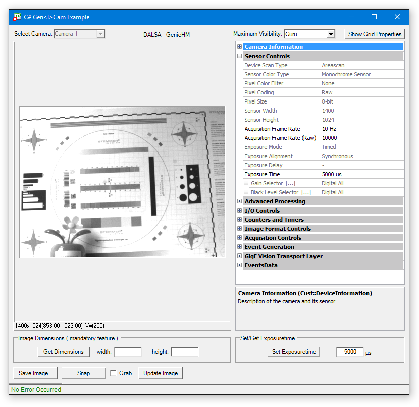
In the Set/Get Exposuretime Area the exposuretime is read out from the camera if available. Then you can set the exposuretime in this area. In the Image Dimensions area it is possible to read out the Image Dimensions of the connected camera. This are mandatory features which means that they are available on every GenICam compliant camera. The exposuretime instead is not a mandatory feature. Because of this the nodenames for the exposuretime from the camera can also be different. And then it is possible that you can't set or get the exposuretime because this example uses the recommended nodenames for the exposuretime feature.
Location
Startmenu: Common Vision Blox -> Hardware -> GenICam -> C# GenICam Example
Path: %CVB%Tutorial\Hardware\GenICam\CS.NET\CSGenICamExample
Functions Used
NMInfoAsString,
NMGetNode,
NRegisterUpdate,
NInfoAsInteger,
NGetAsInteger,
NSetAsInteger


")