|
|
Common Vision Blox 14.0
|
|
|
Common Vision Blox 14.0
|
 |  |  | ||
 |  | |||
 | ||||
 | ||||
 |  |  |  |  |
The GenICam™ standard (Generic Interface for Cameras) provides a generic software interface for any kind of vision acquisition devices, independent of their hardware interface. It allows access to devices such as cameras or strobe controllers via a standardised interface, no matter which technology-such as GigE Vision, CameraLink, CameraLink HS, CoaXPress or USB3 Vision-is used.
The GenICam standard consists of different modules, each addressing a specific part of a typical vision system:
For more information refer the EMVA homepage: http://www.emva.org/standards-technology/genicam/
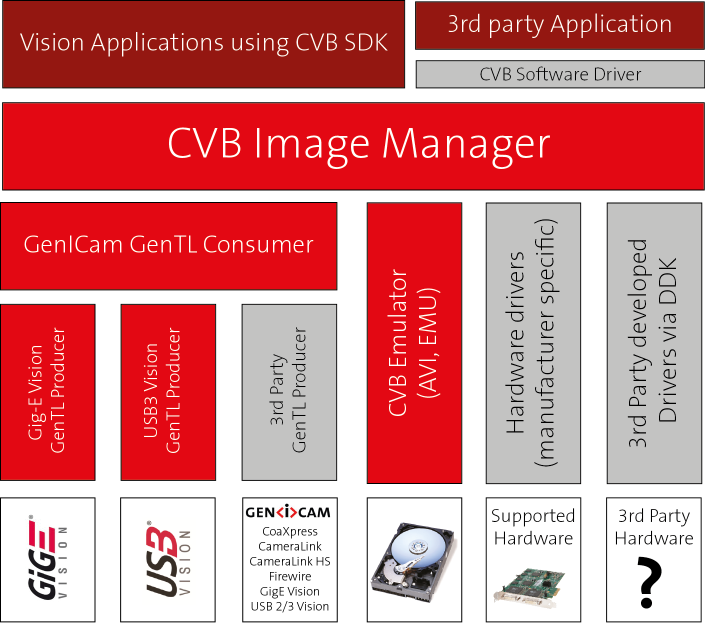
Compared to manufacturer specific SDKs Common Vision Blox with GenICam offers manufacturer independence and increased image acquisition functionality. Hardware compatibility is accomplished by using CVB's vin driver technology supporting various acquisition technologies including any GenICam GenTL provider (transport layer). Being the GenICam GenTL standard maintainers we can assure best support for compliant GenTL providers.
The following acquisition device interface standards are generally used for new applications:
For cameras to connect directly to a PC:
For the fastest applications that will require a frame grabber:
The hardware independent architecture of CVB requires a video interface file (vin) to be loaded, when an image acquisition device is used.
The *.vin format is proprietary to CVB and supports a wide variety of interfaces for acquisition, line scan acquisition, triggered acquisition and many more.
| CVB included | Description | File Info | Interworking with |
|---|---|---|---|
| GenICam GenTL Consumer for interchangeable Transport Layer usage | GenICam Video Interface Driver | GenICam.vin %CVB%Drivers (Windows) /opt/cvb/drivers (Linux) | any GenTL Producer |
| GigE Vision GenTL Producer | Transport Layer for GigE | GEVTL.cti GENICAM_GENTL64_PATH, GENICAM_GENTL32_PATH | compliant devices |
| USB3 Vision GenTL Producer | Transport Layer for USB3 | CVUSBTL.cti GENICAM_GENTL64_PATH, GENICAM_GENTL32_PATH | compliant devices |
| Emulator | Hardware emulation | *.avi , *.emu | video files |
The video interface (vin) file format is used for all Common Vision Blox drivers. There are vin-files available for a vast range of different image acquisition devices like frame grabbers, cameras or vision systems. Please refer to the CVB download area for driver download matching the CVB versions.
| Additional supported hardware integrations | Description | File Info | Download and install for usage with CVB |
|---|---|---|---|
| 3rd party GenTL Producer refer Other Transport Layer Camera Link, Camera Link HS, FireWire (IEEE1394), CoaXPress, USB2, Analogue, Active Silicon Firebird Framegrabber | Transport Layer, can be accessed by GenTL Consumer in CVB due to GenICam compliance | example: Vimba1394TL.cti VimbaCLConfigTL.cti TLActiveSilicon.cti | 1. CVB 2. manufacturer hardware control software (e.g. runtime or SDK) Devices will then appear as a GenICam devices in CVB’s Applications. example: Allied Vision Vimba software for GenICam transport layer support. |
| Manufacturer specific hardware driver for Frame Grabber or Camera integration, developed by STEMMER IMAGING | CVxyz VIN Driver for grabber and cameras without GenICam | example: CVSiSoMe.vin for Silicon Software Frame Grabber, CVXcelera...vin for DALSA Frame Grabber CVuEye.vin for IDS cameras | 1. CVB 2. manufacturer hardware control software (e.g. runtime or SDK) 3. CVB vin-driver for this hardware |
| 3rd party developed drivers | DDK based proprietary driver | *.vin | Hardware supplier |
The majority of vin-files are developed by STEMMER IMAGING, a Driver Developers Kit (DDK) is available for larger image acquisition hardware manufacturers to purchase. For further information on purchasing the DDK please contact STEMMER IMAGING.
| Additional supported software integrations | Description | File Info | Download and install for usage with CVB |
|---|---|---|---|
| CVB Software Driver for 3rd party Applications | Sherlock CVB Driver, Vision Pro CVB Driver | 1. CVB 2. 3rd Party Application (e.g. IPD Sherlock, Cognex Vision Pro) 3. CVB software driver for this product example: Sherlock CVB driver, VisionPro CVB driver 4. Vision Hardware dependant Driver and Software (refer above) | |
Supported Operating systems and other system requirements for the GenICam driver
For more details please refer to Release Notes chapter.
If possible use the newest CVB version because of many improvements in the GenICam package.
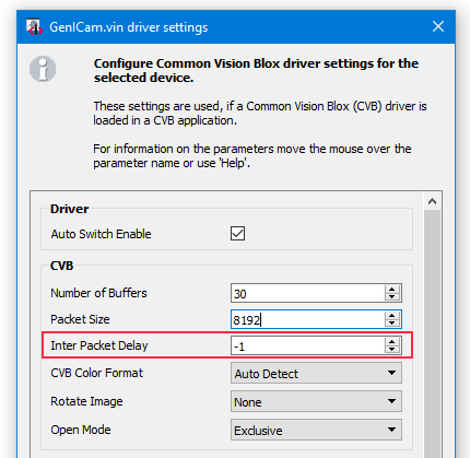
The GenICam driver GenICam.vin uses the driver specific initialization file GenICam.ini to set up the communication and data handling parameters for its associated devices.
Its default location is
The GenICam.ini file can be changed and saved over the menu opened by Options button in GenICamBrowser Configured Devices:
![]()
Driver and Device Options for the selected device can be saved by clicking the Save Button.
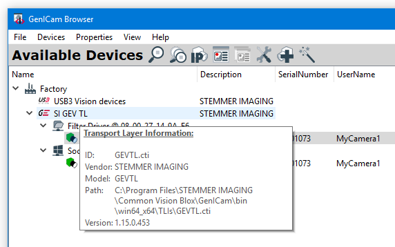
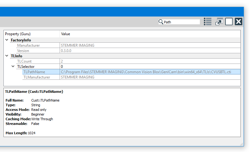
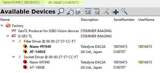
Information about all supported Transport Layer (*.cti files) can be found in GenICam Browser in the Available Devices window. In this example the STEMMER IMAGING CVB USB3 Vision (CVUSBTL) and the GigE Vision Transport Layer (GEVTL) are available.
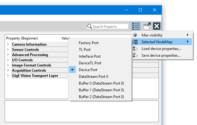
A nodemap displayed in the Property Grid is part of the Transport Layer and therefore available for all GenICam compliant cameras. Nodemaps are based on the acquisition hardware *.xml file and structured in different ports:
DevicePort
DeviceTLPort
DataStreamPort
FactoryPort
InterfacePort
TLPort
If the device has no *.xml file in its memory a "Nodemap unavailable" message is returned when the device is opened. Be aware that setting a correct XML file for the device is a precondition, if there are problems, refer trouble shooting section.
For Parameter Reference refer to GenICam Standard, SFNC (Standard Features Naming Convention) part.
Get access to the nodemaps via GenICam Browser:
This is the port, which contains the nodemap for the device (remote device). It is the normal nodemap for all device features and is used by default and is returned with the CV GenApi function NMHGetNodeMap().
Programmatically it is referenced in the header file (iDC_GenICam.h) over the enumeration DC_PARAM_GENICAM with: DC_DEVICE_PORT_NODEMAP = 0x00000500
This is the port, which contains the nodemap for the device module of the GenTL. The device module represents the GenTL Producers' proxy for one physical remote device. The responsibility of the device module is to enable the communication with the remote device and to enumerate and instantiate data stream modules. The device module also presents signaling- and module configuration capabilities.
Programmatically it is referenced in the header file (iDC_GenICam.h) over the enumeration DC_PARAM_GENICAM with: DC_DEVICE_NODEMAP = 0x00000400
This is the port, which contains the nodemap for the Data Stream module. A single (image) data stream from the device is represented by the Data Stream module. The purpose of this module is to provide the acquisition engine and to maintain the internal buffer pool. Beside that the Data Stream module also presents Signaling and module configuration capabilities.
Programmatically it is referenced in the header file (iDC_GenICam.h) over the enumeration DC_PARAM_GENICAM with: DC_DATASTREAM_NODEMAP = 0x00000600
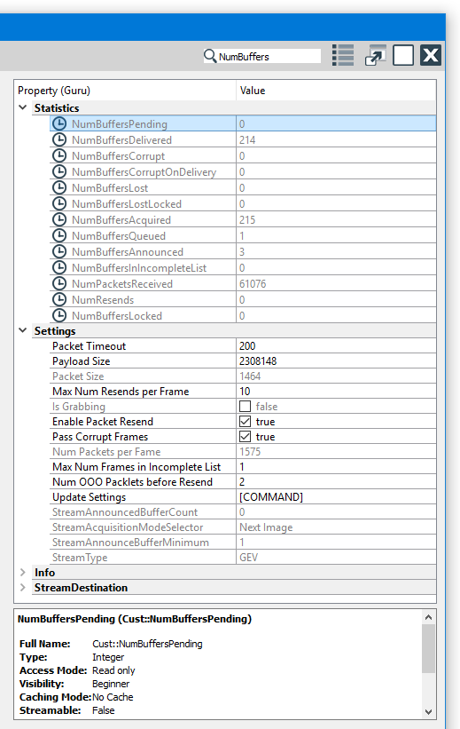
This is a command, which refreshes the more expensive statistics (those without a polling icon).
Number of buffers which, at a given point in time, can take new data. Only queued buffers can take new image data. Buffers, which are not queued, are basically locked. In CVB, before a G2Grab starts, all announced buffers are also queued for acquisition. So until the first image starts the NumBuffersQueued = NumBuffersAnnounced. While the first image is transferred the number of queued images is one less than at the start. After the first image finished until the first call to G2Wait the NumBuffersQueued = NumBuffersAnnounced-1 and the pending frames = 1. After G2Wait and before the second image starts NumBuffersQueued = NumBuffersAnnounced-1, delivered buffers=1, pending frames=0. And so on.
These are the buffers known to the GenTL which can hold image data. Only known buffers can be queued (and thus filled with incoming frame data). This has direct influence on the amount of memory allocated by the driver to hold image data.
The number of buffers which have been filled with image data and which are not yet collected by (delivered to) the application (e.g. via G2Wait or ImageSnappedEvent).
Number of buffers which have been started to fill but are not yet done. In case this (internal) incomplete list is full the buffer will, depending on the configuration of the driver, delivered as corrupt buffer to the host application or discarded. In other words this counter indicates that a new frame arrived but the old one is not complete yet due to missing packets. It is only updated when packet resend is enabled.
This is a lost frame counter indicating that an new incoming frame from a camera could not be filled because no buffers where queued. This normally means that the processing is too slow and cannot keep up with the frame-rate of the camera.
Number of images which were corrupt (not complete) when delivered through G2Wait. A corrupt delivered image cannot/will not be completed after delivery.
The number of buffers taken from the input queue. This means the number of frames the GenTL tries to fill with incoming data.
Number of images which were corrupt on arrival in the host no matter if or if not resend requests have been issued. This setting indicates if something is wrong with the transmission. In case the user wants to discard corrupt images he needs to configure his video interface/TL accordingly. A corrupt image is an image which in the first run did not arrive properly. This includes also images which for example had missing packets and which have been completed later on using resend requests. So a corrupt image may not be corrupt on delivery because the transport mechanisms underneath corrected the failure.
This is related to GigE and indicates the number of data packets (not frames) received on the GigE Vision streaming channel. received.
This is related to GigE and indicates the number of resend requests issued by the host. If this number increases it indicates that something is wrong with the data transmission. Possible reasons may be: Settings of the network card, CPU-load on the host, cable/switch problems, bandwidth problems on the Link (only incremented if missing packets occur and packet resend is enabled). Following examples show how to access features within a CVB program.
This is the port which contains the NodeMap for the Factory, which represents the GenICam.vin driver.
Programmatically it is referenced in the header file (iDC_GenICam.h) over the enumeration DC_PARAM_GENICAM with: DC_FACTORY_NODEMAP = 0x00000100
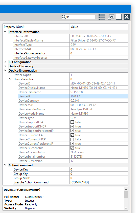
This is the port which contains the NodeMap for the interface module. An interface module represents one physical interface in the system. For Ethernet based Transport Layer technologies this would be a Network Interface Card (NIC), for a Camera Link based implementation this would be one frame grabber board. The enumeration and instantiation of available devices on this interface is the main role of this module. The interface module also presents signaling and module configuration capabilities.
Programmatically it is referenced in the header file (iDC_GenICam.h) over the enumeration DC_PARAM_GENICAM with: DC_INTERFACE_NODEMAP = 0x00000300
python Code Example: DeviceConfiguration example
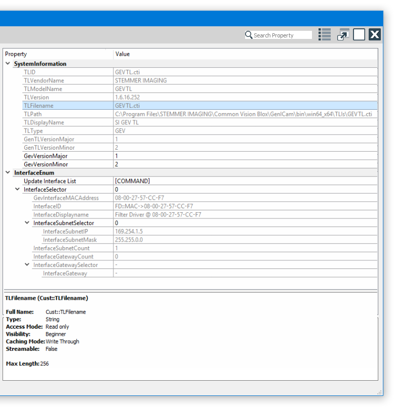
This is the port which contains the NodeMap for the system module. For every GenTL Consumer the system module as the root of the hierarchy is the entry point to a GenTL Producer software driver. It represents the whole system (not global, just the whole system of the GenTL Producer driver) on the host side from the GenTL libraries point of view. The main task of the system module is to enumerate and instantiate available interfaces covered by the implementation. The system module also provides signaling capability and configuration of the module's internal functionality.
Programmatically it is referenced in the header file (iDC_GenICam.h) over the enumeration DC_PARAM_GENICAM with: DC_TL_NODEMAP = 0x00000200
A GenICam device is always equipped with a certain version of firmware. Every firmware revision has a dedicated XML file to describe the abilities and features of the device. When opening a camera its XML file is going to be read when the device is plugged in for the first time. The downloaded structure serves as the base for the property grid (Nodemap).
To set a new XML file, run the EditBindings console application. With this console application you can see the current linked *.xml file and you can add/delete/bind a new XML file. For future access to the device, the XML file is saved within a database on the host machine and loaded automatically whenever the camera is connected. Camera xml files for Common Vision Blox are saved under %CVBDATA%GenICam\xml\Registry\Files (Windows) and /var/opt/cvb/GenICam/xml (Linux). It is possible that an XML file is changed over time by the vendor to simplify the interface, while the firmware remains the same. It then suffices to set the new XML file with the CVB EditBindings application since the internal functionality remains the same. In case a new revision of camera firmware is published, it is generally distributed by STEMMER IMAGING with further remarks about the changes made as well as the installation procedure. If you don't find an appropriate update please contact our technical support.
To be able to acquire images from GenICam compliant devices the CVB GenICam driver (GenICam.vin) has to be installed on your system. This is done by default with every CVB installation.
The complete CVB setup includes the GenICam Driver automatically and installs all necessary libraries, controls, sample programs in source code, documentation, the vin-driver, the siNetFilter GigE Vision Filter Driver and the transport layers for GigE Vision and USB 3 Vision.
Download the installation package to a local drive.
 Do not install over the network. Since the network connection will be reset during the installation, this will result in a damaged driver setup.
Windows:
Install CVB by executing the CommonVisionBlox*.exe1
- Reboot
After installation the
- following environment variables are set
%CVB% > ProgramFiles
%CVBDATA% > ProgramData
%CVBCONFIG% > ProgramData since CVB 13
- GenICam.vin file is available in %CVB%Drivers
- GenICam.ini file is available in %CVBDATA%Drivers
- applications and tutorials are under %CVB%Applications and %CVB%Tutorial
- GenICamBrowser is in Start Menu STEMMER IMAGING Common Vision Blox and under %CVB%Applications
1 Hints for installation of the STEMMER IMAGING Filter Driver for GigE: The setup will try to install the siNetFilter GigE Vision Filter Driver. Press the “Proceed Installation” button to install the driver for all NICs. This may appear several times depending on the number of NICs in your system. In some cases the setup will not be able to install the driver at this time and the installation will continue after the next reboot. More detailed information about the siFilter Driver Installation can be found in the siFilter Driver Installation section.
Linux (refer also GettingStardedGuide.txt):
Install CVB with write access (chmod a+x *.sh) by executing in terminal window:
> ./install_cvb.sh 2
- Reboot
After CVB installation the
- GenICam.vin file is available in /opt/cvb/drivers
- GenICam.ini file is available in /etc/opt/cvb/drivers
- documentation can be found under /opt/cvb/doc
- tutorials can be found under /opt/cvb/tutorial
To run an example it has to compiled first with sudo make. Maybe gcc has to be installed before.
- Libraries are in /opt/cvb/lib
- GenICamBrowseris in /opt/cvb/bin
Run the GenICamBrowser with ./GenICamBrowser
2 If no camera is available or the acquisition does not work with USB3 Vision devices, follow the steps in Linux GettingStartedGuide.txt (refer installation package).
In case of GenICam compliant hardware, used with Common Vision Blox, the GenICam Browser is to be taken or the GenICam.vin driver has to be loaded by other applications/tutorials. If needed, install the Grabber SDK or Runtime (e.g. Teledyne Dalsa CamExpert, Silicon Software MicroDisplay) and device driver provided by the device manufacturer.
Note: Please check the CVB Web for drivers and updates or contact technical support. If updated versions are available, they are distributed together with an updated User Guide and a list of new features or fixes in the Release Notes.
Registry entries concerning the use of the Common Vision Blox GenICam driver are located at the following key in the Windows registry:
HKEY_LOCAL_MACHINE\SOFTWARE\COMMON VISION BLOX\IMAGE MANAGER\STEMMER IMAGING
The following entry exists: CV GenICam Driver INI-File=$(CVB)\Drivers\GenICam.ini
Details regarding the INI-file are explained here.
The GenICam Browser is used to detect connected devices via available Transport Layers and configure them.
GenICam Browser can be opened with:
After detection and configuration the specific device and driver data have to be saved as Configured Devices. To open the Common Vision Blox (CVB) *.vin driver (CVB video interface) at least one device has to be stored and accessible in Configured Devices (green camera icon).
To test the correct device settings close the device in GenICam Browser and open a Common Vision Blox application (e.g. CVB Viewer or one of the Image Manager tutorials)
To access the devices and load the *.vin device driver all CVB tools and tutorials can be used in the same way.
Device specific features as Turbo Drive can be tested and used in tools and tutorials accessing *.vin driver only, not with GenICam Browser, which uses the Transport Layer.
All CVB GenICam core elements are represented in GenICam Browser:
The GenICam standard provides a wide range of configurable parameters, the most important ones are described on the following pages. These parameters are generally subdivided into mandatory features as well as custom ones, which might not be implemented by every manufacturer. This can result in minor differences in the setup of specific functionality between device vendors.
The GenICam.vin Common Vision Blox GenICam driver reads the specific driver configuration from the file GenICam.ini which can be found under:
Refer also CVB Driver Structure chapter for overview of driver configuration options and differences.
On the following pages there are guides for:
Getting Started with the CVB Configurator and follow the checklist for configuration of:
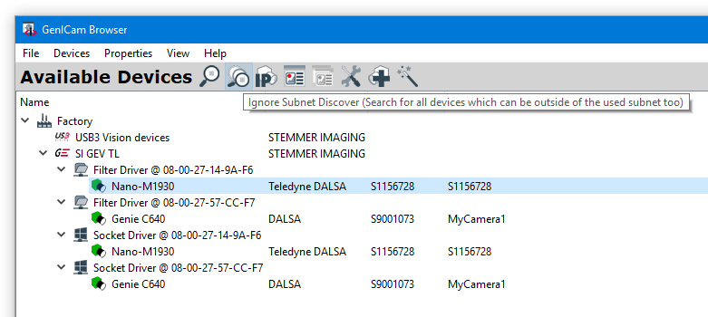
After starting GenICam Browser for the first time, the available transport layer (TL), available interfaces and devices are listed in a tree view under Available Devices.
To search for available devices and to refresh the Available Devices tree use the Ignore Subnet Discover button. All available devices show up in Available Devices window. If you are using Linux, there are further actions to be taken. Please have a look at the Ignore Subnet Discover on Linux section.
Hardware relevant configuration steps have to be considered, refer:
GigE Vision
USB3 Vision
Other Transport Layer
Different camera symbol colors representing status information. Not displayed devices pointing to missing interface configuration. For details refer GenICam Browser User Guide in Help menu or hints in the GenICam Browser Logging window.
The Linux kernel usually filters broadcasts into wrong subnets. In order to spot cameras with an IP not matching the subnet of the NIC, this feature is essential though. Luckily you can turn the filtering off. Create a bash (.sh) file with following content and execute it.
Even though this may only last until the next reboot, it is good practice to enable the strict filtering again, after setting a valid IP, by writing a 1 to the config. Especially if your PC is connected to the internet or any other untrustworthy network!
Disabling the filter only for the NIC the camera is connected to in the first place is even safer:
For more information concern reading this introduction to Reverse Path Filtering.
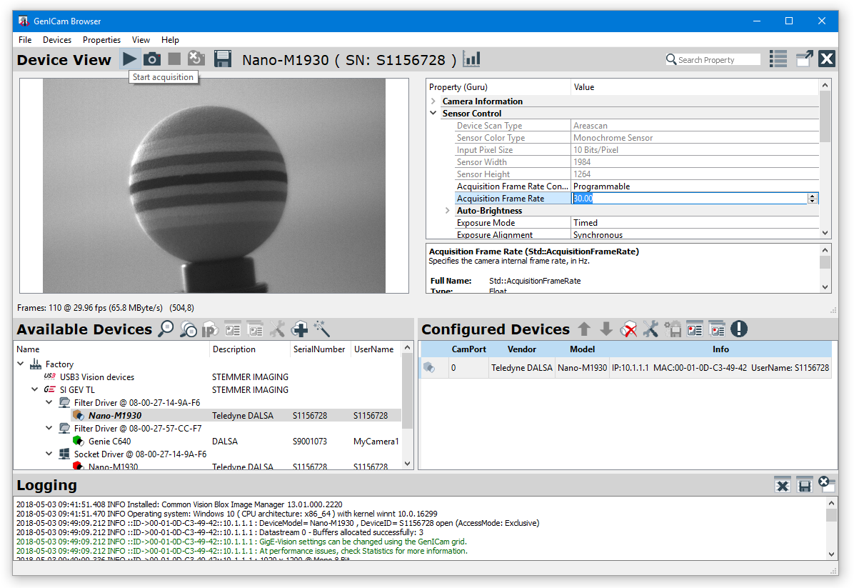
Doubleclick on the device (use Filter Driver in Windows and Socket Driver in Linux), which has a green camera icon now, or use the Open Device button to get a live view and to configure the device. The device will be opened in the Device View. On the left side a live image is shown, on the right side you will find the property grid to configure the device. In Available Devices the device shows up with an orange icon (device is open). In the Logging part of the application you get some detailed information. To get a single image use the Snap button, to start the acquisition press the Grab button and to stop the acquisition press the Stop button.
Driver Specific Configuration Files
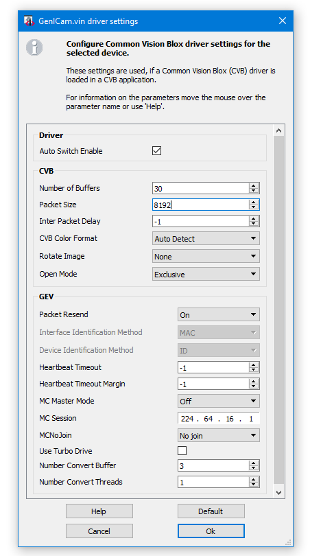
The driver specific configuration file is the GeniCam.ini-file (refer %CVBDATA%Drivers directory). To set up and store the communication and data handling parameters for GenICam, this ini-file is required. This file is updated automatically when changing parameters in the Device Options for configured devices in GenICam Browser. So normally there is no need to manually edit the ini-file.
Options stored in GenICam.ini (example for GigE device)
| [SYSTEM] | Settings which apply to all devices of that kind in the system |
|---|---|
| NumCameras=1 | Number of cameras |
| CreateAutoIni=0 | internally used for the Device Configurator |
| AutoSwitchEnable=0 | If set to 1 the driver loads the first configured device which is available. e.g. if the first device is not available AutoSwitchEnable=0 would cause an Error Loading Image file. If set to 1 it would show the second device with no error. |
| DeviceUpdateTimeout=-1 | |
| AutoConfigExecuted=1 | internally used for the Device Configurator |
| [CHANNNEL_0] | Settings which apply only to the first device [DEV0]. Please add additional sections for [DEV1] ... according to your system setup |
| TL=GevTL.cti | Link to used transport layer |
| Interface=FD::Mac->00:AB:11:22:CD:33 | FD:: FilterDriver is used SD:: SocketDriver is used Mac->Interface MAC-Address |
| Device=::ID->00:AB:11:22:CD:33::192.168.1.1 | Device Identification: ID, IP, MAC or Username Default is configuration via ID e.g. ::ID->00-00-00-00-00-00::10.0.1.1, which is a combination of MAC and IP address. |
| NumBuffer=3 | Number of buffers allocated at vin startup: Acquiring images and using image processing functions with high CPU workload simultaneously can still lead to lost frames. Use the G2GetGrabStatus CVB-function to show the lost frames. To avoid lost images it is possible to increase the image buffer. In times of high workloads the images will be buffered. CVB takes the oldest image for processing. This principle just works for tasks where the high workload of the CPU is not steady so that CVB is capable of emptying the buffers from time to time. As a rule of thumb use as many buffers as the frames you acquire per second. Then the driver buffers one second. |
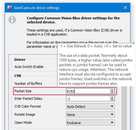
| PacketSize=-1 | Size of a data packet. For optimized performance adapt to NIC Jumbo Frame (Jumbo Packet) size. -1 = Default (1500 is used as packet size default value). 0 = Auto >1 = Set to value Can be used to reduce cpu usage. Attention: The network interface must also be configured to accept jumbo frames. Used switches in the network have to support jumbo frames also. |
| InterPacketDelay=-1 | Sets the delay between data packets. Adapt to NIC optimized Inter Packet delay. An increase in this delay can reduce the peak bandwidth of a device. 1 Use Default >= 0 Set to specified Value |
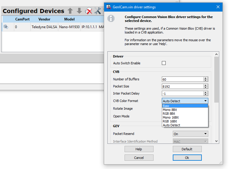
| PixelFormat=5 | Pixel format of the CVB Image 0 = Raw image what ever the device delivers 1 = Mono 8Bit 2 = RGB 8Bit 3 = Mono 16Bit 4 = RGB 16Bit 5 = Auto Detect (default) eg converts high bit to 8 bit see chapter Color Formats and Pixeldepth option 2: For a bayer color camera the driver would do an 2x2 RGB conversion |
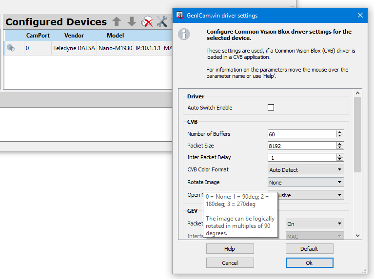
| RotateImage=0 | The image can be logically rotated in multiples of 90°: 0 = None 1 = 90deg 2 = 180deg 3 = 270deg |
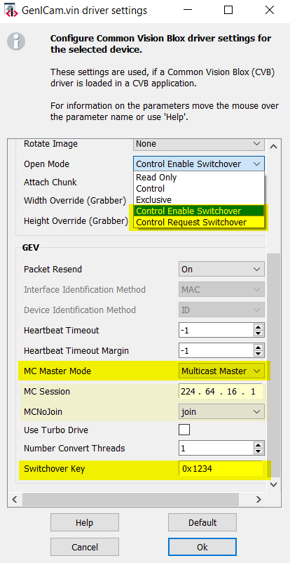
| AccessMode=4 | The mode to open a device: 2 - Read Only: used when the device is slave in a Multicast setup (not controllable by application) 3 - Control : used when the device is the Multicast Master (controlled by application) 4 - Exclusive: peer to peer connection. This is the normal mode. 5 - Control with Enable Switchover: used when the device is the Multicast Master (controlled by application) and switchover should be enabled 6 - Control with Switchover Request: used when the application wants to take over the control of the device (switchover has to be enabled by another application and switchover key is required for authentication). |
| AttachChunk=0 | Enable or disable chunk data. |
| WidthOverride=-1 | Optional grabber only value if the Transport Layer overrides width from the device. Please use this value thoughtfully! |
| HeightOverride=-1 | Optional grabber only value if the Transport Layer overrides height from the device. Please use this value thoughtfully! |
| PacketResend=1 | Activate or deactivate the packet resend mechanism for the specific device. Since CVB 12.00.000 the packet resend is activated by default. |
| HeartbeatTimeout=-1 | This timeout controls how long the device waits for a signal from the application until it cancels that connection to that application. -1 Use Default >= 500 Set to specified value |
| MCMasterMode=0 | 1 = Device is Multicast Master. If Master mode is choosen, AccessMode must one of the control modes, otherwise the driver will not load correctly. |
| MCSession=224.64.16.1 | The IP Address of the Multicast session. |
| MCNoJoin=1 | Multicast join (0) / no join (1). With join enabled (NoJoin = 0) the control device joins the stream. Set to 0 to get images on all devices. |
| UseTurboDrive=0 | Enable (1) or Disable (0) Turbo Drive (for Dalsa cameras supporting this feature only). |
| NumConvertThreads=1 | Number of threads used to convert / decompress images in parallel (min = 1, max = 16) |
| SwitchoverKey=0x0 | The authentication key (hexadecimal key 16bit unsigned) to take over control in Multicast switchover session. |
User Sets
Every GenICam camera supports a functionality to save at least one User Set over the User Set Selector, i.e. a user exclusive camera features configuration. User configurations can be set and also be chosen to be the default configuration loaded when the camera is switched on with setting the Power-Up Configuration Selector.
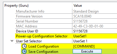
The factory configuration is not touched at all, such that restoring the initial settings at a later point in time is possible with Device Reset. 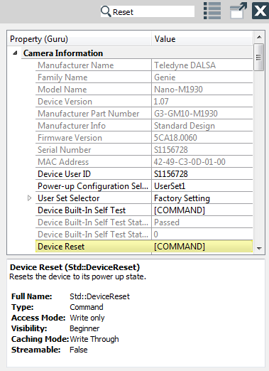
Color Formats and Pixeldepth
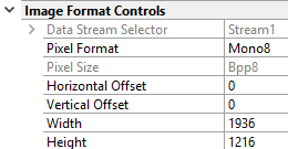
Changing the image resolution
How to rotate the image from the camera
Converting images from Color cameras with bayer sensors
White Balance
By default, CVB automatically detects the correct preprocessing for the pixel format / color format the camera delivers (default parameter Auto Detect at Device Options > CVB Color Format menu or direct in the GenICam.ini-file). For example if the camera delivers 8 Bit Bayer data, CVB converts the image to a RGB 24 image using an 2x2 RGB conversion. If a 8 Bit Mono image is detected, the raw 8 Bit image is used.
Another example would be for a camera delivering 10 Bit monochrome data which needs to be scaled down to 8 Bit monochrome data. In this case you could set the Pixel Format in the driver to 8 Bit monochrome (also with Device Options > CVB Color Format menu or direct in the GenICam.ini-file).
Supported source color formats:
When the Pixel Format is set to Raw in the driver, all source formats are supported. In this case the image is not converted after acquisition.
Supported conversions:
All Color formats can be converted to RGB 24. All Mono formats can be converted to Mono 8. For hints dealing with high bit images ( > 8 Bit) in CVB please refer to the Common Vision Blox Manual.
If you change a setting in the camera which changes the resolution or pixel size of the image, you need to update the image object by using the IImageRect Interface. Refer this section for more information.
For most of the supported image acquisition devices (cameras or frame grabbers) it is possible to rotate the image fast via an entry in Device Options -> Rotate Image.
Supported values are:
0: Rotate 0 degrees
1: Rotate 90 degrees
2: Rotate 180 degrees
3: Rotate 270 degrees
CVB also offers general functions for rotating images (e.g. RotateImage, CreateMatrixTransformedImage, CreateMatrixTransformedImageEx). Those functions take some time to perform.
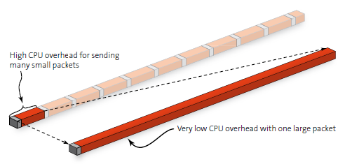
Debayering (conversion into RGB images) can be done with different methods, depending on the camera model and the drivers in use. It is not recommended to convert frames to RGB in cameras before transmission if the frame rate is extremely high. This is because raw Bayer requires only 8/10 Bit versus the 24 Bit necessary for RGB.
![]()
Please select the desired Pixel Format via the Property Grid - or your own CVB Application and save the format you choosed via the parameter set User Sets.
| User Set Selector | User Set1 |
| User Set Default Selector | User Set1 ( default configuration ) |
| User Set Save | Execute Button |
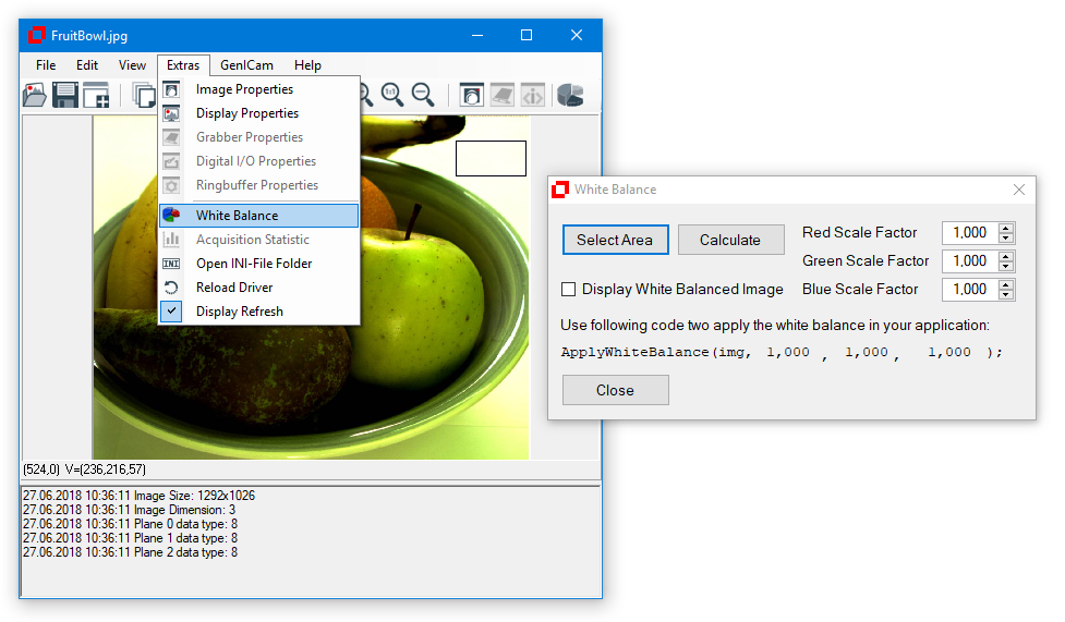
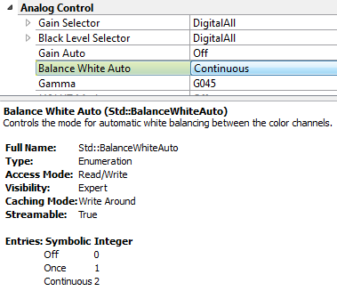
Some cameras do not support white balance, other cameras can only use white balance with RGB output with a reduced frame rate. For such cases it is necessary to transfer the Bayer image and execute white balance in extra software programs. CVB provides the white balance functionality in the library with the Image Manager functions CalculateWhiteBalance and ApplyWhiteBalance.
To test these functions the Common Vision Blox Viewer can be used:
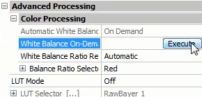
For cameras supporting white balance based on GenICam BalanceWhiteAuto parameter there are settings via the NodeMap available, such as:
This chapter contains descriptions on setting up features like
If you want to open multiple devices, you can click on the device (use Filter Driver in Windows and Socket Driver in Linux), which has a green camera icon and use the button 'Open additional device'. When another device is already open you will be asked, if you want to keep other devices open.

If you load the GenICam.vin driver into your CVB Tutorial/CVB application (for example CVB Viewer), the driver boots with whatever camera is entered as Device0 in your GenICam ini-file. To access other cameras in your application, you have to change the CamPort/Device selection. CVB Viewer allows live acquisition and display from multiple cameras parallel, for port change refer following picture. 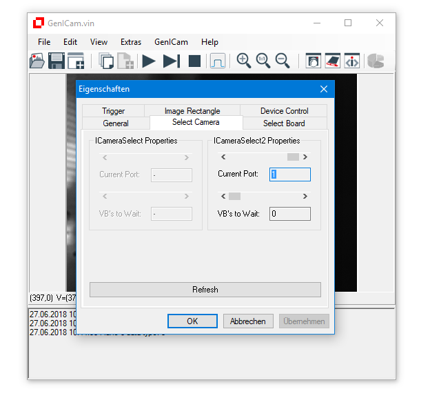
If you plugged off the camera designated as Device0 you might not see any image. If you intend to access the next available camera in this case, set the AutoSwitchEnable to "1" in the GenICam initialization file.
Refer also:
Note
In your application you can use the ICameraSelect2 Interface to select between multiple cameras. The index maps to the order number specified in your GenICam.ini-file.
The GenICam driver uses a driver specific initialization file to set up the communication and data handling parameters for its associated devices. Its default location is %CVBDATA%Drivers. If a different file should be used for GenICam setup, the path entry in the registry must be adjusted.
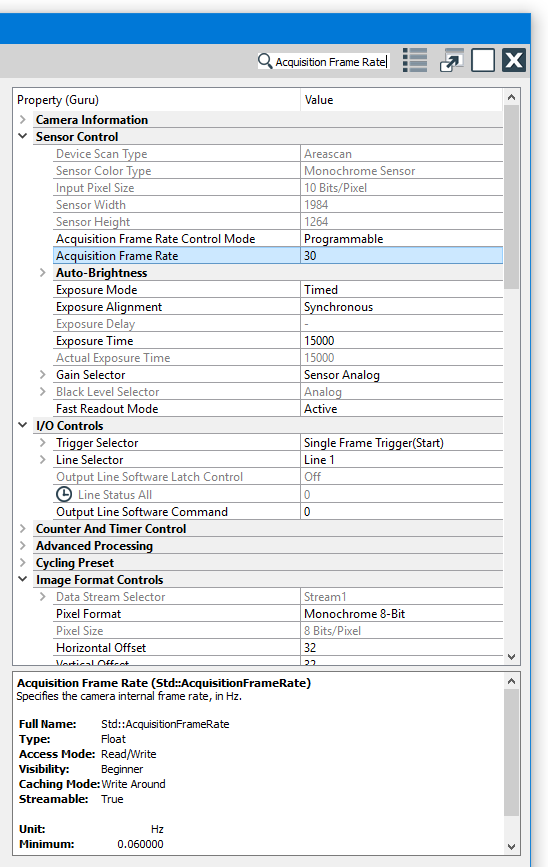
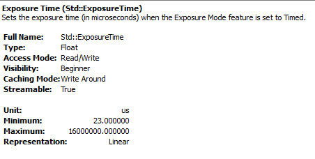
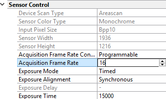
The exposure time is not a mandatory GenICam feature. Nodenames for the camera exposure time might also be different between model from different manufacturers. The number of acquirable images of course depends on how long each single frame is going to be exposed. As long as the Acquisition Frame Rate value is on its maximum, the camera will try to acquire as much frames as possible. The upper limit of possible frames is however set by the exposure time. Exposure time can be directly set as a duration in µs. Increasing the exposure time reduces the acquisition frame rate and vice versa!
ExposureMode = Timed / TriggerWith / TriggerControlled
Timed : exposure with defined duration (ExposureTime), start with FrameStart or LineStart
TriggerWith : exposure time defined by frame or line trigger signal width.
RisingEdge or LevelHigh -> exposure duration equals trigger HIGH,
FallingEdge or LevelLow -> exposure duration equals trigger LOW
TriggerControlled : exposure duration based on one or more trigger signals
ExposureTime = <value>us
Exposure time in CVB: The CV Gen API itself provides no dedicated function to dynamically set the Exposure Time directly. Please implement Exposure Time settings as described in the Common Vision Box Manual in the chapter Image Manager - GenICam Library.
As the values for standard exposure times (in us) are too low for LTE applications, the exposure time can be set with Pulse Width Control. Shutter mode will be invalidated automatically when using Pulse Width Control.
Acquisition and Trigger Control: First, the Exposure Mode has to be be set to "Pulse Width Control", because the values for standard exposure times (in us) are too low for LTE applications. This automatically invalidates the Shutter Mode, i.e. its configuration has no influence on image acquisition anymore.
Digital I/O: To set the correct signal routing, one of the freely programmable signal lines (Line Source) has to be selected, in this case "Pulse Generator 0".
Pulse Generators: To configure the signal itself with the duration of exposure, its Start Point, Length and End Point can be modified according to individual timing requirements. With a Pixel Clock of 60 MHz the exposure time is about 300 ms in example below. The computation of the exposure time can be found in the camera's manual in chapter "Pulse generators". To run Pulse Width Control with Software Trigger the settings are as follows:
| Exposure Mode | Pulse-width control |
| Line Selector | Pulse Generator 0 |
| Line Source | Software Trigger 0 |
| Pulse Generator Selector | Pulse Generator 0 |
| Clear Mode for the Pulse | High / Low Level | Rising / Falling Edge |
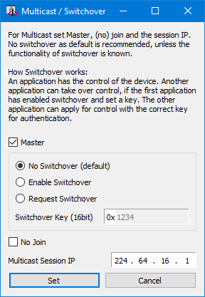
For Multicast Switchover and Unconditional Streaming checkout the according topic.
Common Vision Blox supports Multicast. With Multicast, it is possible to send packets to all devices in the same network. In IPv4, the address range from 224.0.0.0 to 239.255.255.255 is reserved for Multicast. By Joining, the master will also join the Multicast session and be able to receive a stream. If NoJoin is set, the master will not be part of the multicast session and only act as device controller without a stream. The configuration can be done using the GenTL or the CVB GenICam driver. For additional use of the feature Turbo Drive, which is supported by all Genie Nano cameras, the configuration has to be done with the CVB GenICam driver, because the Turbo Drive feature is implemented in the driver.
Tested Software versions:
Operating system: Ubuntu 20.04 || Windows 10
Common Vision Blox: 13.04.002
For Multicast with Socket Driver (SD) please consider the Network Configuration, especially for Multicast with Socket Driver.
If your goal is to just setup and stream a camera to all network devices, this is the right configuration for you.
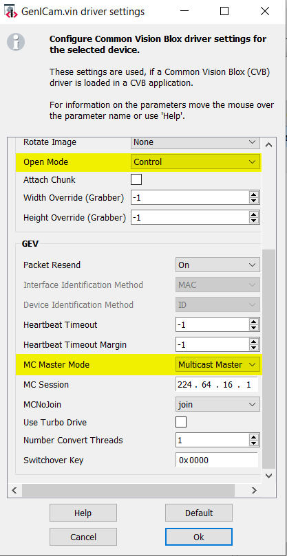
Master (Read/Write) configuration:
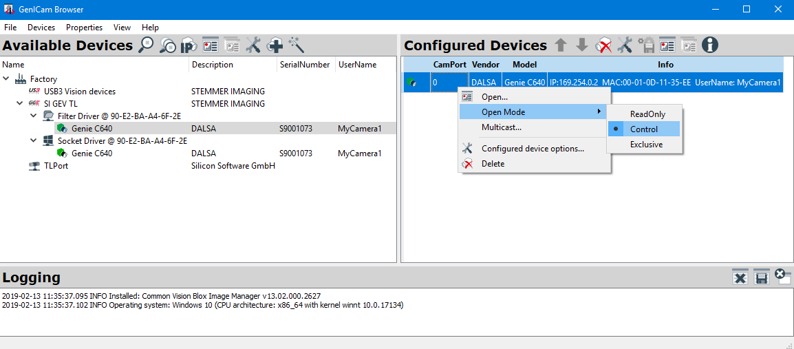
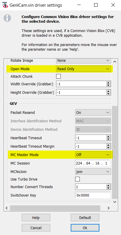
Slave (ReadOnly) configuration:
If your goal is to setup and stream a camera to all network devices, but the camera should be opened with a tool like the CVB Viewer by loading the GenICam.vin driver or by calling a Cvb::DeviceFactory::Open("path/to/GenICam.vin"), use this configuration.
To configure the GenICam.ini file there are three viable options:
Configuration and saving options top right of the GenICam Browser:
Master (Read/Write) configuration:
| Slave (ReadOnly) configuration:
|
|
|
B) Using Discovery properties in code (advanced)
If your goal is to set up and stream a camera to all network devices and the camera should be completely managed by code or you wish to use the Switchover feature in an unconditional streaming context (code only), prefer this configuration over 2)A) because 2)A) requires to change the GenICam.ini file, which makes no sense in a code only scenario.
When a programming only solution is desired, above properties can be set to the discovered device. Please note that there might be minor differences depending on the loaded driver (GevSD/GevFD) which can be chosen upon device discovery. To add multicast properties to the device before it is opened, call .SetParameter(...) on the device that should be opened. For a reference of possible parameters and spelling, please refer to the GenICam.ini file entries, which are mirrored in their behavior here. Also configuring like described under 1) or 2)A) is possible and then copying the parameters and values for use with SetParameter().
For normal Multicast (without Switchover and Unconditional Streaming) checkout the according topic.
For Multicast with Socket Driver (SD) please consider the Network Configuration, especially for Multicast with Socket Driver.
When using Multicast, a special feature combination using switchover and unconditional streaming makes it possible to keep the camera running on application crashes and re-set the master with configuration access for the device. This would normally not be possible, as an application crash of the master application would lead to a headless camera which is only controlled by the now unavailable host (if unconditional streaming is available but no switchover) or would stop the camera from streaming (if switchover is available but not unconditional streaming). For availability of both switchover and unconditional streaming, please refer to your specific camera model and device firmware. If the camera supports both feature, the following will describe the setup using CVB:
All configurations can be copied from above setup (take your pick) with following additions:
To enable switchover, set Enable Switchover (in 1)) or set Open Mode to Control Enable Switchover in 2)A) or call .SetParameter(CVB_LIT("AccessMode"), CVB_LIT("5")); on the device that should be opened.
By enabling switchover, the device is in access mode "control". If a second application now tries to connect to the device, only the access modes read only and Request Switchover aka. Control Request Switchover, or .SetParameter(CVB_LIT("AccessMode"), CVB_LIT("6")); are sensible access modes. Trying to gain exclusive access on a switchover enabled device is also possible, but all other devices will be locked out from the device connection then.
Additionally, the switchover feature supports a Switchover Key which is a 16 bit value entered as four characters. The key is set when initially opening the device with the switchover enable command and is saved to the device. If a switchover request is received, the Switchover Key set along the switchover request must match the key used on the initial device opening with the switchover enable command. Otherwise no access is granted. The key remains valid until the device is completely closed.
To set the Switchover Key using the device discovery, use: .SetParameter(CVB_LIT("SwitchoverKey"), CVB_LIT("0x0000"));
If no Switchover Key is set, the key will be 0 in all cases, which also works just fine. The idea behind the key is more of an additional barrier to shield against involuntary external access to a GEV connected device.
To take control of a switchover enabled device, set Request Switchover (in 1)) or set Open Mode to Control Request Switchover in 2)A) or call .SetParameter(CVB_LIT("AccessMode"), CVB_LIT("6")); on the device that should be opened.
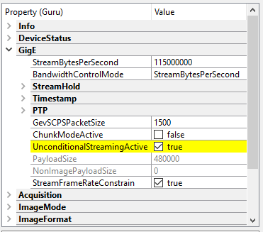
To enable unconditional streaming tick the option in the device node map or set the node map option on the opened device in code.
When a programming only solution is desired, above properties can be set to the discovered device. Please note that there might be minor differences depending on the loaded driver (GevSD/GevFD) which can be chosen upon device discovery. To add multicast properties to the device before it is opened, call .SetParameter(...) on the device that should be opened. For a reference of possible parameters and spelling, please refer to the GenICam.ini file entries, which are mirrored in their behavior here.
There are two ways to trigger the image in the camera. Either hardware (electrical signal to the camera’s trigger input) or software (set a feature in the camera within controlling software to take an image). The GenICam standard part SNFC therefore defines feature semantics and the behavior for trigger modes.
Acquisition Trigger Modes
Trigger Source Types (with TriggerMode=On)
A platform independent C++ code example for software trigger can be found in the MultiOSConsole Example (Camera.cpp) of the Image Manager:
Windows: %CVB%Tutorial\Image Manager\VC\VCMultiOSConsole
Linux: /opt/cvb/tutorial/ImageManager/ComplexMultiOSConsoleExample
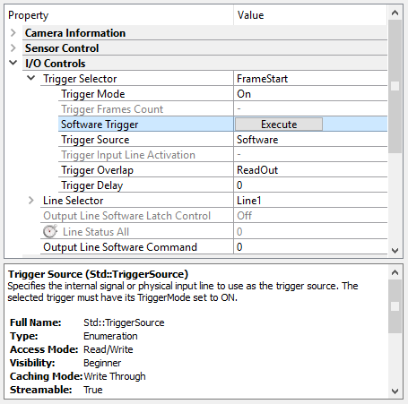
To activate it, the Trigger Mode must be set to "On" . Trigger Source must be set to "Software" and Exposure Mode to "Timed". For a quick test, the Trigger Software field in the GenICam Property Grid provides an Execute button to send a signal.
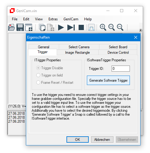
To test the configuration within a software solution, the trigger can be either sent via the the GenAPI (refer CVB Manual chapter Image Manager - GenICam Library) or the ISoftwareTrigger interface (e.g. VB.NET Grabber OCX Example) which is shown in CVB tutorials. Also it can be used with CVB Viewer:
On arrival of a software signal, the image will be captured and processed by the application. Be aware that there exists a standard timout interval. If the delay between the trigger signals is too large, this will result in Timout Error messages (CVB error #4). Change the timeout value to a higher value in this case.
For details regarding the ISoftwareTrigger Interface please refer to the SDK -> Supported Interfaces chapter.
Since the trigger is obtained from an external device in this case, Trigger Mode must be set to "On". At the same time the Trigger Source must be changed to "Line x" (refer also pin assignment for standard Hirose in camera manuals) and Line x has to be configured to be an Input.
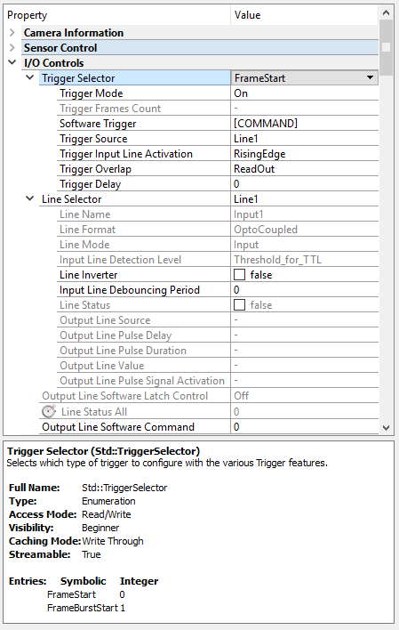
Example configuration (GenICam SFNC notation) for an external triggered acquisition that will start the capture of each frame on the rising edge of the signal incoming from Line 1:
| TriggerSelector | = FrameStart; |
| TriggerMode | = On; |
| TriggerActivation | = RisingEdge; |
| TriggerSource | = Line1; |
| LineSelector | = Line1; |
| LineMode | = Input; |
| LineInverter | = False; |
With these settings the camera is in "active mode" for each incoming trigger in Line 1. Refer device manuals for trigger details.
Example configuration within a camera property grid (parameter notation may differ between GenICam SFNC and cameras):
To test the chosen configuration with a CVB application, the camera must be set to Grab mode. On arrival of an external signal, the image will be captured and processed by the application. Be aware that there exists a standard timout interval. If the delay between external trigger signals is too large, this will result in Timeout Error messages (CVB error #4). Change the timeout value to a higher value in this case.
Synchronize the cameras to expose at the same time
This can be achieved by connecting the same external trigger signal to one of the digital inputs of each camera or using PTP for GigE.
Some cameras can be connected as a Daisy Chain (e.g. Allied Vision FireWire models). The Master camera is triggering the slave camera(s).
The configuration of the cameras is done in CVB Property Grid:
Master camera settings:
Slave camera settings:
There may be a delay between the exposure output of the master camera and starting of the exposure of the slave camera and also a jitter between the trigger signal on the input of the slave camera and starting the exposure. It is recommended to externally trigger both cameras, if the cameras should operate synchronously with higher frame rates to avoid the delay.
From the user's perspective, the GigE Vision standard consists of three parts:
Device Discovery
As this is a network protocol, devices must be found first. For this, the GigE Vision standard allows users to search for cameras in a sub-network. Cameras, in this case, play a passive part and respond to queries. The response to a query also contains information on the devices discovered, e.g., names and versions.
GVCP (GigE Vision Control Protocol)
The core purpose of the GVCP is the control of cameras on a register basis. An application reads out and writes individual data blocks. Every data block (register) represents one or several features such as the exposure time for the sensor.
GVSP (GigE Vision Streaming Protocol)
GVSP provides a protocol for streaming non-compressed and - since version 2.0 - also compressed data streams.
The performance level of a GigE Vision system depends strongly on the hardware and software components and their configuration. The maximum data rate from 125 MByte/s is just a theoretical number as within this 125 MByte also data are send which are not directly related to the image. A realistic, stable payload value for image calculation is 100MByte/s.
Below and in the next chapters performance considerations and settings are described.
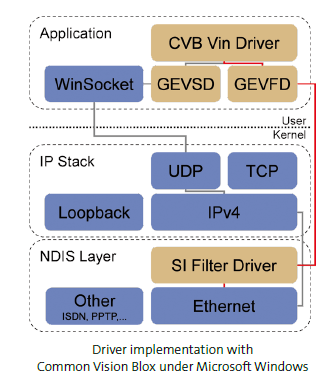
Due to the fact that the GigE Vision standard is a mere protocol description, generic driver implementations are possible. The simplest and most portable solution is to use the operating system IP network stack. This is often referred to as socket driver because all large operating systems provide the socket interface for network access (e.g. Windows Sockets or POSIX Sockets). However, normally this solution offers the poorest performance. Improvements are available by adopting the so-called high performance or filter drivers. Typical of both driver types is that they bypass the generic operating system network stack to provide better performance by specialised implementation. The driver runs in the operating system kernel and can therefore work on network data with the highest priority. Image data compilation already occurs in the driver and the image as a whole is transferred to the application. Because the network stack is bypassed, less CPU capacity is bound up and data security improves (fewer lost packages) due to the higher CPU priority. Even if the implementation of both driver types is different (driver directly for one network chip or generically for all network cards in the Windows filter stack), both offer the same improved performance for the protocol structure of GigE Vision.
Single camera on a dedicated NIC
The most simple setup is a single camera on a dedicated NIC (no other network traffic) with a point to point network connection. In order to retrieve their IP address, GEV cameras are configured to use DHCP by default and the same applies when configuring a NIC under Microsoft Windows. If there is no DHCP server (which is likely on a point to point connection) the camera and the NIC will, after a while, fall back to a mode called LLA. In this mode both ends (camera and host) will pick a random IP address. If you want to eliminate the time delay until they fall back to LLA you have to assign static IP addresses. In this type of scenario the bandwidth and data latency is optimal. Depending on which components are used and your system specification you can expect to get over 100MB/sec.
Single camera on a corporate Network
With a camera connected to a corporate network the scenario is only slightly different since a corporate network will usually have a DHCP server and both the camera and the PC will get their IP address from it. On the other hand, you cannot be sure that there won’t be other cameras on the network. In large set-ups there is a good chance that the system will address the wrong device. The bandwidth usage on such a system might be critical since it will affect the corporate network.
Multiple cameras on a single NIC
In this setup the IP address assignment is similar to the previous sections. The main concern in this case is the bandwidth. If in such a system the peak bandwidth is above one Gbit you have to make sure that either the switches can buffer enough data to sustain that peak or you have to limit the bandwidth of the cameras by setting the InterPacket delay of the cameras. The InterPacket delay is a mandatory bootstrap register of a GEV device. It can be set using the CV GenApiGrid Control (NodeMap) and then saving this to the profile of the camera to restore the setting on the next boot up. For some cameras this is controlled over the StreamBytesPerSecond parameter.
Multiple cameras on multiple NICs
With multiple network interfaces you get better performance than with a single NIC but the IP-address assignment is a little bit more complicated. You have to make sure that each NIC is running on a separate subnet. If you have two NIC's running on the same subnet under windows, one cannot predict which NIC will be used to send the packet. If the packet is sent via the “wrong” NIC which is not connected to the correct camera, this camera will never see the packet and a connection will not be established.
The overall performance of a GigE Vision system setup depends on the network hardware components (network interface card, switch, camera, cable) as well as their appropriate configuration, which is described in the following chapters. Additionally to this there are some camera dependent GigE network features, which are described here.
TCP/IP Settings
Set the Camera IP address
Performance Settings
Jumbo Packets
Firewall and VPN Settings
InterPacket Delay
Turbo Drive
Precision Time Protocol
Link Aggregation
siFilter Driver
Multicast with Socket Driver
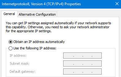
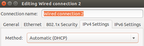
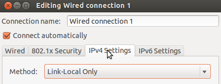
To establish a connection to any GigE Vision device, both the Network Interface Card NIC and the GigE Vision device must have a valid IP in the same subnet range. Addresses can be assigned both dynamically and statically.
| Windows: | Linux: |
|---|---|
|
|
| Windows: | Linux: |
|---|---|
|
|
GigE Vision must be identified by an unique IP address. Addresses can be assigned both dynamically and statically. Per default, GigE cameras try to establish a connection to the host machine based on dynamic addresses. When plugged in, the camera first sends out a number of DHCP requests. If no answer is received within a fixed period of time (usually 60 s), the systems tries to auto configure the network via the LLA (Link Local Address) addressing scheme. LLA only works when both links are configured to be set dynamically (DHCP).
After starting GenICam Browser for the first time, the available transport layers (TL), available interfaces and devices are listed in a tree view under Available Devices. To search for available devices and to refresh the Available Devices tree use the Discover button. All available devices show up as green cameras. GigE devices are displayed under SI GEV TL:
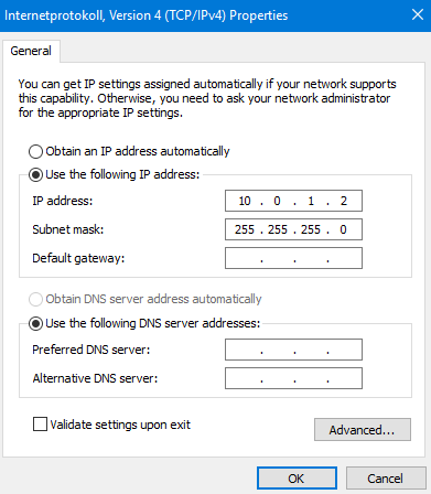
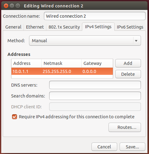
Static IP addressing is available in two different forms:
In both cases, the address must be set within the NIC and with an application interfacing the camera.
| Windows: Network and Internet, Network Connections | Linux: Network connections |
|---|---|
|
|
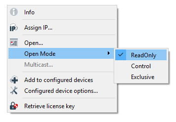
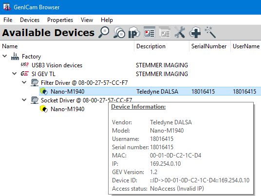
The camera may have another IP address configured or set as default. In the below example on the GenICam Browser the camera is found in another subnet (yellow icon). The camera IP address info can be read by left clicking the camera symbol or right mouse click -> Info. Access status here is NoAccess (Invalid IP).
Setting the IP address matching the NIC configuration is to be done over the configuration in Available Devices menu:
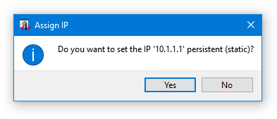
Force IP (fix over this power cycle):
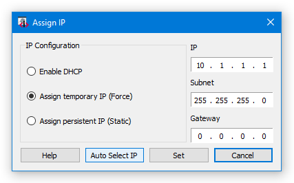
After each temporary IP setting it will be asked for storing it as static IP to keep the setting over restarts. Select 'No' in in case of temporary IP, valid for this power cycle. With 'Yes' the IP address is set as static.
Static IP (always fix):
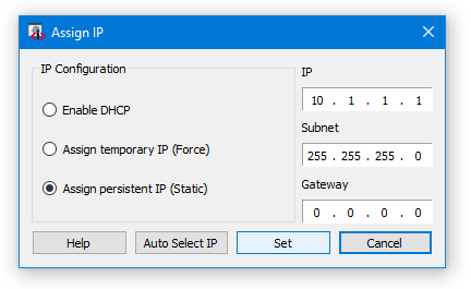
With both settings the camera icon has to be green with Access status: ReadWrite.
There are mandatory
which influence the performance of the system and the stability of the data transfer over the network card. This section will describe which settings should be optimized for maximum performance and minimal CPU usage. But it shows also which features can have massive impact in the stability of the data transfer. Wrong settings can result in a huge amount of lost packets that even whole images are discarded.
The variance of NIC performance settings depends on the used operating system and is described in detail in the following sections.
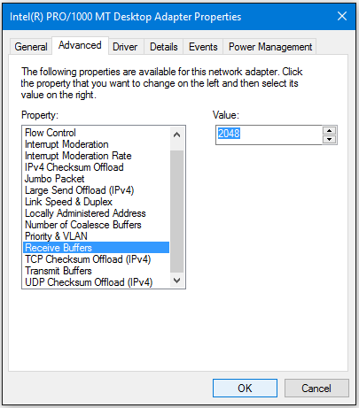
Receive Buffers
Sets the number of buffers used by the driver when copying data to the protocol memory. Increasing this value can enhance the receive performance, but also consumes system memory. Receive Descriptors are data segments that enable the adapter to allocate received packets to memory. Each received packet requires one Receive Descriptor, and each descriptor uses 2KB of memory.
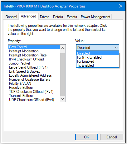
Flow Control
Enables adapters to generate or respond to flow control frames, which help regulate network traffic.
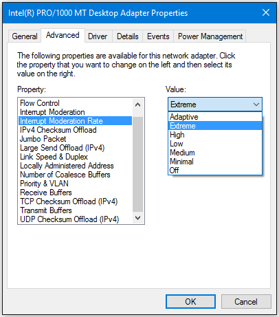
Interrupt Moderation Rate
Sets the Interrupt Throttle Rate (ITR), the rate at which the controller moderates interrupts. The default setting is optimized for common configurations. Changing this setting can improve network performance on certain network and system configurations. When an event occurs, the adapter generates an interrupt which allows the driver to handle the packet. At greater link speeds, more interrupts are created, and CPU rates also increase. This results in poor system performance. When you use a higher ITR setting, the interrupt rate is lower, and the result is better system performance. NOTE: A higher ITR rate also means the driver has more latency in handling packets. If the adapter is handling many small packets, lower the ITR so the driver is more responsive to incoming and outgoing packets.
Jumbo Frames / Jumbo Packets
Enables or disables Jumbo Frame capability. If large packets make up the majority of traffic and more latency can be tolerated, Jumbo Frames can reduce CPU utilization and improve wire efficiency. Jumbo frames have a strong impact on the performance of the GigE Vision system. Jumbo frames are packages with more than the Ethernet MTU (Maximum Transmission Unit) of 1500 bytes. Less header data is transmitted, which allows more capacity to be available for user data.
Usage Considerations
Enable Jumbo Frames only if devices across the network support them and are configured to use the same frame size. When setting up Jumbo Frames all involved network devices, be aware that different network devices calculate Jumbo Frame sizes differently. Some devices include the header information in the frame size while others do not. Intel adapters do not include header information in the frame size. Jumbo Frames only support TCP/IP. Using Jumbo frames at 10 or 100 Mb/s can result in poor performance or loss of link.
When configuring Jumbo Frames on a switch, set the frame size 4 bytes higher for CRC, plus four bytes if using VLANs or QoS packet tagging.
Jumbo Frames can cause lost packets or frames when activated in the network card and the camera. But this is normally a side effect caused by the other settings mentioned before, which is only visible with Jumbo Frames. This means that, if you have trouble when using Jumbo Frames, try to find the cause in the previously mentioned settings instead of deactivating the Jumbo Frames.
Interrupt Throtteling (10 GigE only)
This parameter should be changed only if you observe performance problems with 10 GigE devices. Windows throttling mechanism Because multimedia programs require more resources, the Windows networking stack implements a throttling mechanism to restrict the processing of non-multimedia network traffic to 10 packets per millisecond.
To optimize the network card under Windows open the Network Properties Dialog (Start->Control Panel->Network Connections), right click on the network connection used. Select "Properties” from the context menu to get the Windows network configuration dialog. Depending on the network card driver, some of the settings described below may occur under a separate dialog page.
Receive Buffers
This parameter has to be set to the maximum available value. If it is too low you can loose huge amount of packets while streaming images
If your network card does not have this option you have to update your network card driver.
If it is not available with the newest driver use another network card.
Flow Control
This parameter has to be disabled. This feature regulates the network traffic which is something we do not want while streaming images.
Interrupt Moderation Rate
For this feature there are no general rules available which setting has to be used. It depends on the network card and the internal bandwidth of the system. If you want to have the lowest CPU load then you have to use the maximum value (Extreme). But with some systems we saw problems with this setting. Then you can loose packets or even whole frames. On some systems also low values can cause these problems. If you have problems with lost packets or lost frames, change this setting to Off. This is the most secure setting - but also the setting with the highest CPU load.
Jumbo Frames / Jumbo Packets
Jumbo Frames are necessary when the maximum network bandwidth is needed. E.g. when using a fast camera or a high resolution camera. Because of this the recommendation is to always use Jumbo Frames when possible.
NOTE: When activated in the network card this does not mean that Jumbo Frames are used. This only means that the network card can handle Jumbo Frames.
To really use Jumbo Frames this has to be activated in the camera by setting the packet size to the appropriate value. The appropriate value depends on the maximum available packet size in the camera and the maximum setting in the network card. As recommendation use 8192 as PacketSize if supported by camera and network card, it was used very often without problems. Normally, if Jumbo Frames are disabled, this does not cause problems with lost packets or lost frames. But as the camera is not able to send the images as fast as they are acquired from the sensor you can have a visible delay in the live image. On the other hand Jumbo Frames can cause lost packets or frames when activated in the network card and the camera. But this is normally a side effect caused by the other settings mentioned before, which is only visible with Jumbo Frames. This means that if you have trouble when using Jumbo Frames try to find the cause in the previously mentioned settings instead of deactivating the Jumbo Frames.
Interrupt Throtteling (10 GigE only)
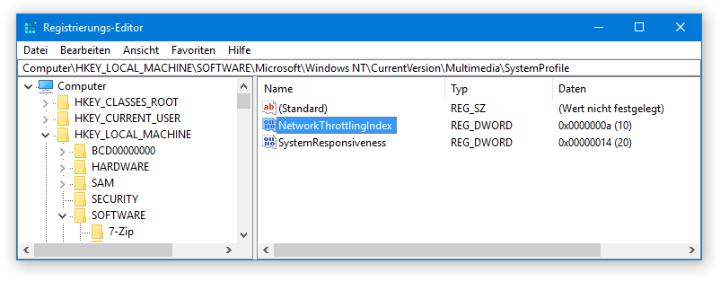
The throttling will come into effect only when you are running multimedia programs that are time sensitive. However, this throttling mechanism can potentially cause a decrease in network performance during the active multimedia playback period. This decrease in performance is likely to occur only on high speed networks that are saturated to maximum capacity. By default, the value for the NetworkThrottlingIndex registry entry is set to 10.
Refer Registry entry:
HKEY_LOCAL_MACHINE\SOFTWARE\Microsoft\Windows NT\CurrentVersion\Multimedia\SystemProfile\
Name: NetworkThrottlingIndex
Value type: DWORD
Value data: From integer 1 through integer 70 (Decimal) (Decimal)
When the NetworkThrottlingIndex registry entry does not exist, the behavior resembles the default behavior. Network throttling can be completely turned off by setting the value to FFFFFFFF (hexadecimal). You must restart the computer after you make a change to the value of the NetworkThrottlingIndex registry entry.
To optimize the network card under Linux open the Network Connections Dialog or with direct terminal commands. Using the dialog window the "Wired connection x” from the list has to be selected and the "Edit" button to has be used.
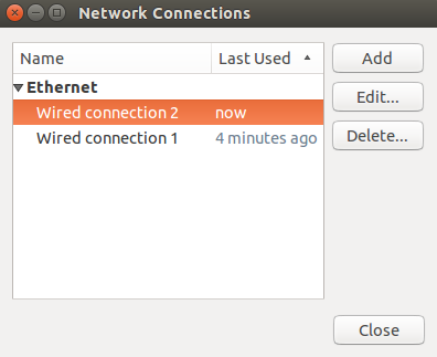
Depending on the network card driver, some of the settings described below may occur under a separate dialog page.
Receive Buffers
This parameter has to be set to the maximum available value. If it is too low you can loose huge amount of packets while streaming images. To change the Receive Descriptors on Linux you need to download ethtool from the installed packet manager.
Get Descriptor Information from eth2: > sudo ethtool -g eth2
Set Receive Descriptors of eth2 to 2048: > sudo ethtool -G eth2 rx 2048
Jumbo Frames / Jumbo Packets
Jumbo Frames are necessary when the maximum network bandwidth is needed. E.g. when using a fast camera or a high resolution camera. Because of this the recommendation is to always use Jumbo Frames when possible.
for eth2 set: > sudo ifconfig eth2 mtu 8192 up or with the dialog:
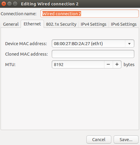
NOTE: When activated in the network card this does not mean that Jumbo Frames are used. This only means that the network card can handle Jumbo Frames. To really use Jumbo Frames this has to be activated in the camera by setting the packet size to the appropriate value. The appropriate value depends on the maximum available packet size in the camera and the maximum setting in the network card. As recommendation use 8192 as PacketSize if supported by camera and network card, it was used very often without problems. Normally, if Jumbo Frames are disabled, this does not cause problems with lost packets or lost frames. But as the camera is not able to send the images as fast as they are acquired from the sensor, you can have a visible delay in the live image.
This section provides a step-by-step instruction to configure a PC and a GigE Vision camera to use jumbo packets. CVB and the Genicam vin-driver needs to be installed and a camera has to be attached and accessible (reachable IP addresses, etc).
1) Set up the NIC to process Jumbo Packets first
a) Set up a NIC to allow Jumbo Packets under Windows
b) Set up a NIC to allow Jumbo Packets under Linux
2) Configuring CVB Genicam Driver and Camera to use Jumbo Packets
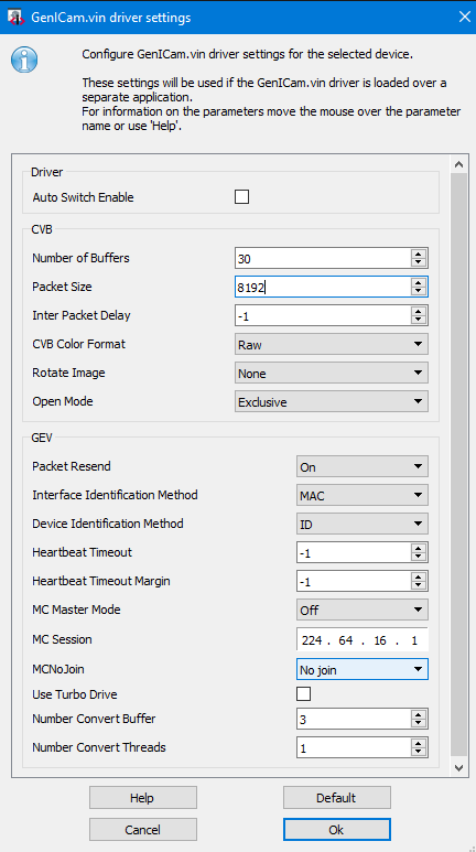
In the GenICam Browser select the device to be configured and click the Device Options button:![]()
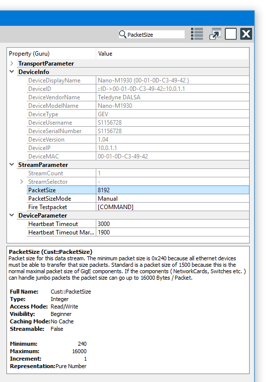
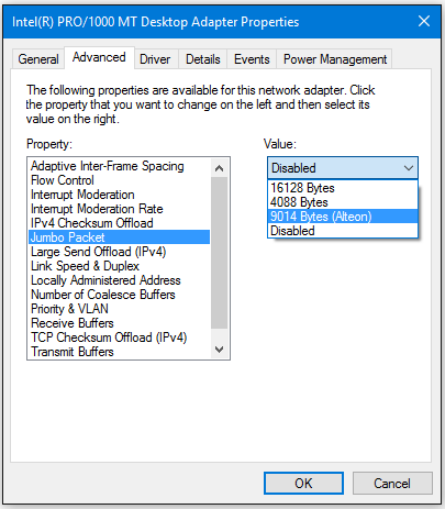
PacketSize parameter can then be changed to the optimum value. Which value should be used depends on the used hardware. A network card has a maximum PacketSize. But also a switch and the camera can have a maximum supported PacketSize. So this parameter must not exceed the maximum PacketSize from one of the used hardware devices. As recommendation use 8192 as Jumbo Frames packet size if supported by camera and network card. Some cameras/network cards/switches only support a maximum PacketSize < 8192. In this case try to harmonize the packet size over all involved components in the setup (camera, switch, network card, driver) to the same value.
Now you can set the size of the packets with the Packet Size parameter Device options dialog which writes the value into the GenICam.ini File.
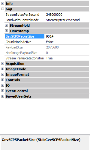
For cameras providing a PacketSize range within specific limits the possible PacketSize values can be determined using the NodeMap (PropertyGrid) in GenICam Browser. To check if a value for PacketSize will be accepted you can always retrieve the info with selecting the PacketSize feature and read the GenICam Node GevSCPSPacketSize info (range between 512 and 9216 in the example below). 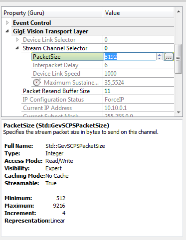
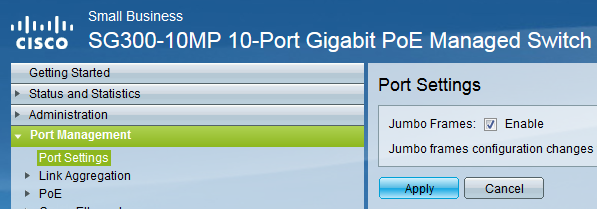
3) When used - enable Jumbo Packets in the switch
Jumbo Frames have to be also enabled when using a switch. When configuring Jumbo Frames on a switch, set the frame size - if requested - 4 bytes higher for CRC, plus four bytes if using VLANs or QoS packet tagging.
Example:
Firewalls can block GigE Vision packets and slow down the system performance. Therefore it is important to disable all firewalls within the camera connection setup when there are connection problems.
The following steps are necessary to switch off the Windows software firewall. For Linux there is no configuration necessary. If you have a hardware firewall (which is available on some NICs) disable those firewalls also.
Also any VPN software running on the system may contain a "Stateful Firewall" which is active even if no tunnel is established. This firewall will block traffic from the camera. In order to work with GEV devices and depending on the VPN software you use, you have to disable your VPN software.
Windows only:
1) Open the Firewall Customize Settings dialog (Start -> Control Panel -> Systems and Security -> Windows Firewall -> Turn Windows Firewall on or off):
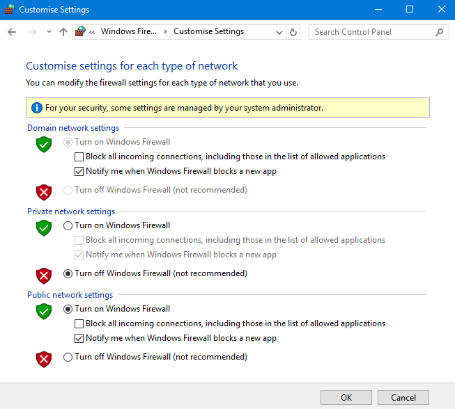
2) Select the "Turn Off Windows Firewall" option to disable the firewall for the type of network which is used for the camera connection.
3) Close all dialogs with the "OK" button to apply the changes.
Consider the settings from GigE Vision -> Network Configuration chapter first.
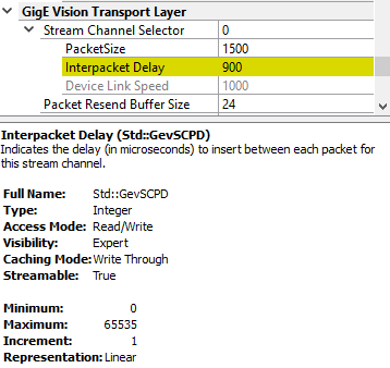
Inter Packet Delay is a parameter to control the data rate from cameras. It is important in multi-camera scenarios.
With Inter Packet Delay cameras can be slowed down while acquisition by adding delays between the sent packets. Other devices are able to send data then too. Inter Packet Delay together with Frame Rate settings and Exposure Time is important as soon as you connect multiple cameras to one network port exceeding together the maximum data rate. Gigabit Ethernet provides 1 Gb/s (Gigabit per second) Bandwith ~ 100 MB/s (Megabytes per second) assuming an optimal network hardware and configuration. In such a system you may have to limit the bandwidth of the cameras by setting the frame rate and the Inter Packet Delay.
If the optimum between Inter Packet Delay and Acquisition Frame Rate is determined, the setting has to be saved in the device options.
Use the Device Options (Driver Options for the selected device) dialog window in GenICam Browser :![]()
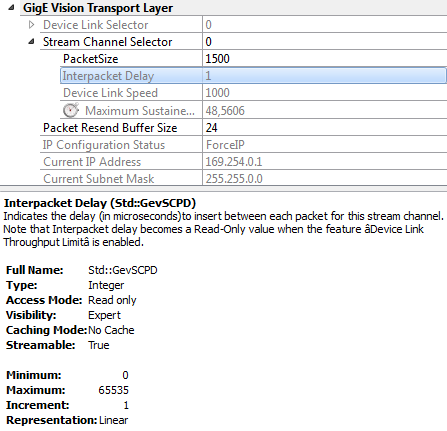
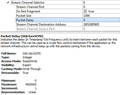
Adding a packet delay between packets during transmission is always based on GenICam Transport Layer Control feature GevSCPD but the representation in camera NodeMaps may differ.
In the following there are some examples how to find the feature.
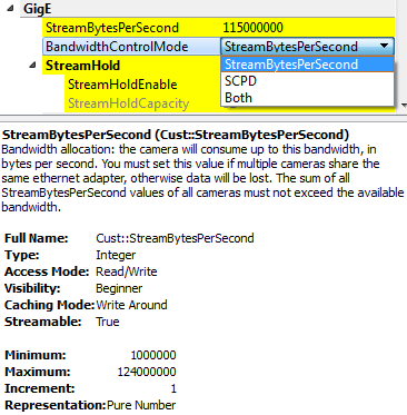
AV GigE example:
They have a feature called "BandwidthControlMode" which is set to "StreamBytesPerSecond" by default. With "StreamBytesPerSecond" the bandwidth which is used by a camera can be changed directly in bytes per second. (e.g. 2 cameras -> StreamBytesPerSecond / 2)
DALSA GigE example:
JAI GigE example:
Currently, only Teledyne Dalsa cameras support this non-standard feature. To make sure your camera supports TurboDrive and to find out the correct TurboDrive version, which can be set later on, please refer to the manual of the firmware currently installed on your Teledyne Dalsa camera.
Specific Teledyne DALSA GigE Vision cameras (e.g. Genie Nano, Linea) supporting a Turbo Transfer mode > TurboDrive feature. This feature allows an increase of the frame rate while loss-less data compression and transmission via Gigabit Ethernet extend the capability of the data throughput (typically 100 MBytes/s) achievable with GigE Vision systems.
Common Vision Blox can handle this Turbo Transfer mode and therefore improve the transfer rates until double the standard throughput (depending on image settings). To set the feature and test it please follow the 2 steps:
1) The feature has to be enabled and saved (for devices supporting TurboDrive) in the GenICam.vin driver:
a) in GenICam Browser Configured Devices -> Device Options dialog window.
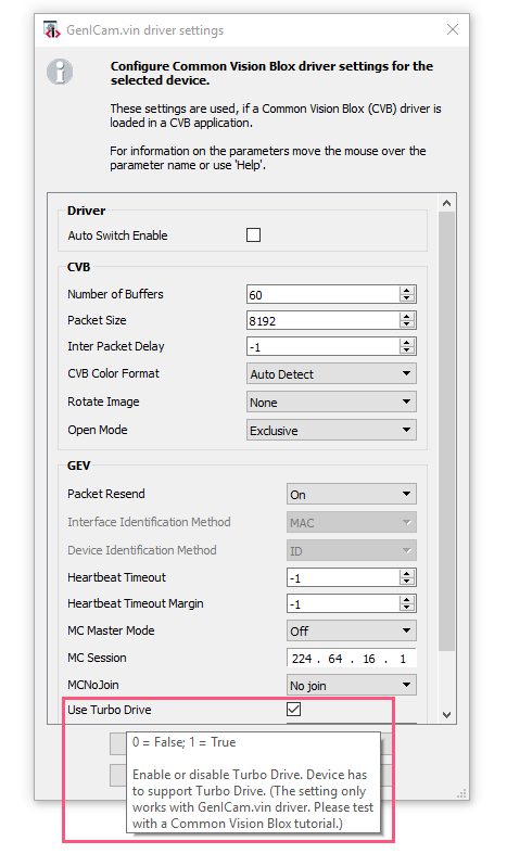
b) Set the Turbo Drive Feature in CVB Viewer within the GenICam.ini file:
2) Turbo Drive can be tested and used in tools and tutorials accessing *.vin driver only, not with GenICam Browser, which uses the Transport Layer.
Therefore use a tutorial from %CVB%Tutorial directory and load the GenICam.vin driver or use the CVB Viewer.
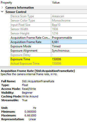
Acquisition Frame Rate (Std::AcquisitionFrameRate)- specifies the camera internal frame rate, in Hz.
Maximum Sustained Frame Rate(Cust::maxSustainedFrameRate) - maximum sustained frame rate that can be achieved by the camera in the current configuration (Resolution, Pixel Format and the camera's internal bandwidth limitations). When TurboDrive is enabled, this value also takes the feature transferAverageBlockSize into account.
Example with Genie Nano M1940, running with Turbo Drive and 64,40 fps:
Data Rate = Resolution * Frame Rate * Bit depth = (1290*1080) * 64,4 fps * 8 Bit = 134 MByte transfered over GigE with Turbo Drive.
Precision time protocol for synchronising several cameras in an Ethernet network
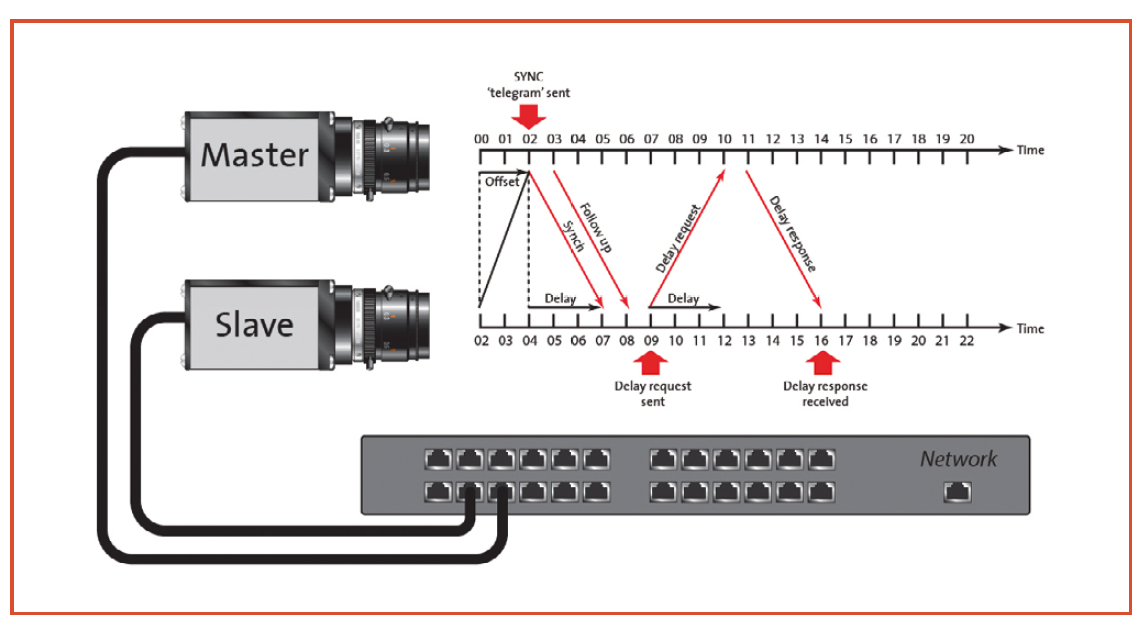
The Precision Time Protocol (PTP) IEEE 1588 enables the exact cycle synchronisation of several devices in an Ethernet system. When the clocks of the devices such as cameras, PCs and sensors, are synchronised, future software image triggers can be synchronised within 2 μs. The GigE Vision 2.0 standard has incorporated PTP IEEE 1588 and warrants maximum compatibility between machine vision hardware and software suppliers in future.
Synchronisation of several cameras cameras supporting PTP are put in a special PTP mode which manages and defines the synchronisation of the camera clocks. The device clock of the master is output with the timestamp of the camera and synchronises several cameras. When the PTP mode is set to 'master', 'slave' or 'auto', the camera synchronisation starts in the network, provided one device is configured as master.
The process starts with the "master" camera which sends a "sync" message via multicast messaging. The "slave" camera calculates the time difference between its internal cycle and that of the master camera. In addition, Delay Request Message (by the slave) and Delay Response Message (by the master) are sent to synchronise the slave clock with the master cycle. When the time difference of the clock is ≤2 μs, the cameras are in synchronous mode. In addition to the exchange of synchronisation messages, the clocks are constantly readjusted by filters and statistical methods in order to eliminate deviations due to the physical layers, the network, repeater or switch.
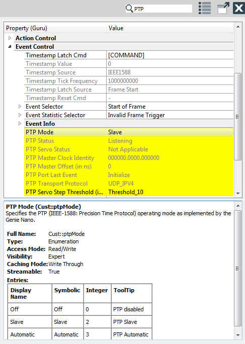
Configure Cameras supporting PTP
Settings in Property Grid (consider camera specific parameter name variance):
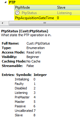
Wait until GigE -> PTP -> PtpStatus has changed from Syncing to Slave. Start acquisition on both cameras.
Set on both cameras the GigE -> PTP -> PtpAcquisitionGateTime to a higher value than GigE -> Timestamp -> GevTimestampValue (get the current GevTimestampValue with GigE -> Timestamp -> GevTimestampControlLatch).
Ensure, that PtpAcquisitionGateTime is still in future after setting on both cameras.
Acquisition stops on both cameras, when PtpAcquisitionGateTime is reached, the cameras run synchronous.
Example: PTP parameter in Nodemap of Dalsa camera
Example: PTP parameter in Nodemap of AV camera
GigE Cameras supporting LAG (Link Aggregate Group)
Cameras supporting LAG (Link Aggregate Group or NIC Teaming) offer 2 GigE ports for image acquisition, so the available bandwith is duplicated to 230 MB/s with optimized network hardware. These ports have to be combined as a Link Aggregate Group. To use the LAG (for example AVT GX-series cameras) the settings of the NIC and the camera have to be adjusted.
NIC (Network Adapter Settings):
Windows:
The LAG group will now be configured. Once completed the properties of the TEAM (LAG) that has just been created will appear. A new Network Connections Icon corresponding to the LAG group is created. After the NIC is prepared for LAG and the camera is connected with both Ethernet cables CVB can be used for the camera set up like it is recommended in the following:
STEP 1
Please perform all CVB GigE Performance settings as recommended for all GigE devices.
STEP 2
STEP 3
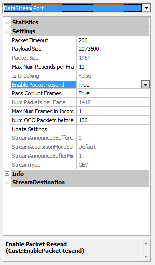
Please take in mind that this two parameters cant be saved in the camera user settings. The settings are done interactively for testing as here described. If you have your own application please check and set the parameters via the Nodemap functionality of the CVB Image Manager. Please have a look at the CVB Manual and the sample code for retrieving Nodemap information from the DataStream Port.
STEP 4 (optional)
For performance and reliability tests please use the Common Vision Blox Viewer. Open the Nodemap DataStream Port and the Device Nodemap via the Genicam menu and configure as described above in STEP 3. Additional please open the Acquisition Statistics via the Extras menu and get information about lost or pending images.
This documentation is for Windows only!
To use Multicast with Socket Driver on Windows (especially on the client side) some settings might be necessary. Generally it is strongly recommended to disable the firewall. Please follow the instructions on Firewall and VPN Settings.
If you still encounter issues, please check following settings:
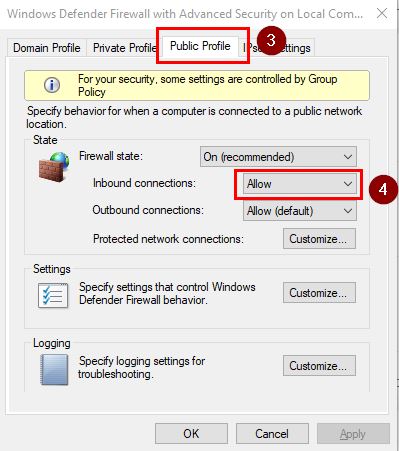
1) Allow Inbound Connections in Public Profile of Windows Firewall
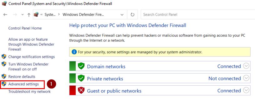
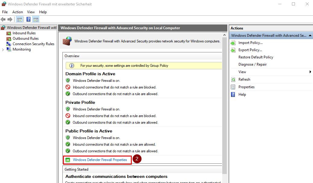
Go to Start -> Control Panel -> Systems and Security -> Windows Firewall, then continue with following steps:
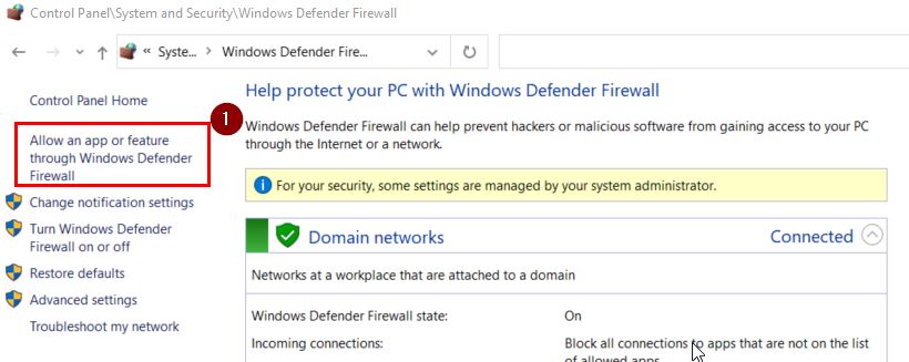
2) Allow an App through Windows Firewall
Go to Start -> Control Panel -> Systems and Security -> Windows Firewall, then continue with following steps:
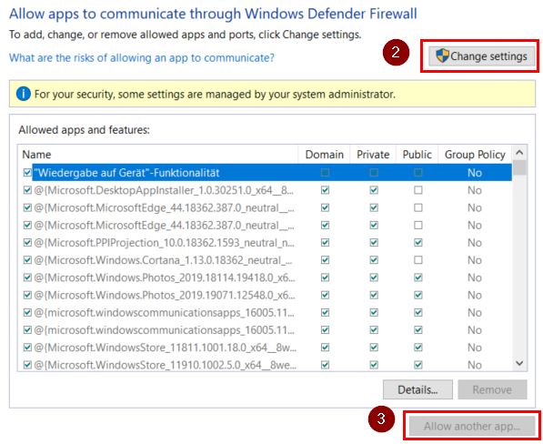
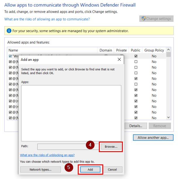
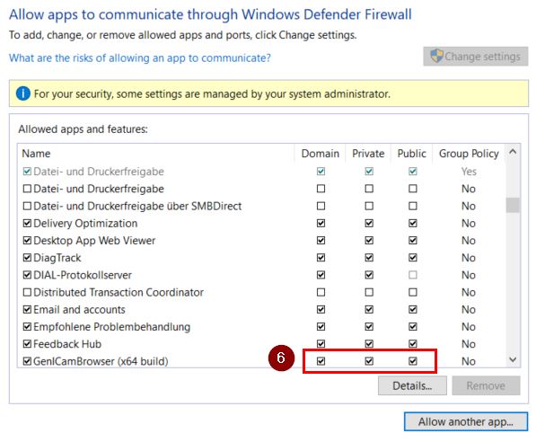
Make sure that the application appears only once in this list.
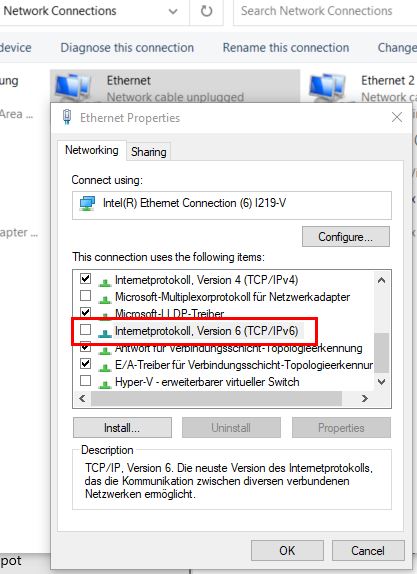
3) Turn off Internet Protocol IPv6
On the used Ethernet connection open its properties and disable IPv6.
4) Deactivate Virtual Boxes
Sometimes Virtual Boxes can have affects on getting images, so the according network connections should be disabled.
Windows only
The siNetFilter Driver for GigE Vision technology is used to bypass the standard network stack (used by the operating system) for all data stream packets. It filters GigE Vision related data packets and transfers them directly to an application-provided data buffer. This greatly reduces the CPU load of the system. All non GigE Vision data stream related packets are unaffected.
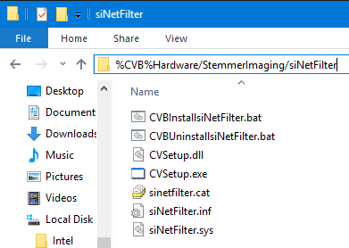
Basically all CVB installations contain the siNetFilter Driver for GigE Vision. (refer %CVB%Hardware/StemmerImaging/siNetFilter)
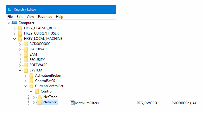
Under certain circumstances it could be necessary to uninstall / reinstall / update / disable or enable the GigE Vision Filter Driver. Consider always the maximum number of Filter Drivers configured on your system when installing filter driver (except Windows 10):
(each NIC counts as one siNetFilter Driver, other Filter Driver maybe installed without recognition, e.g. through VBox, VPN, etc. - so maximum has to be increased)
If you have uninstalled the siNetFilter Driver you can reinstall it.
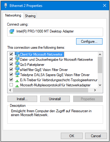
1) Open your Network Properties Dialog (Start -> Control Panel -> Network Connections) right click on the network connection used.
Select "Properties" from the context menu to get the network configuration dialog.
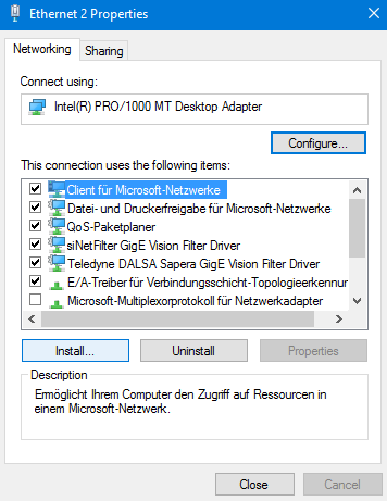
2) Click the "Install" button to open the following dialog.
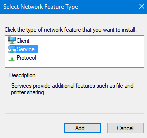
3) Select "Service" and click the "Add" button.
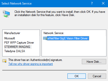
4) Select the siNetFilter Driver and click the “OK” button.
5) The setup will now try to install the siNetFilter Driver.
Press the "Proceed with Installation" button to install the driver for all NICs.
It may appear several times depending on the number of NICs in your system.
6) Close all dialogs with the "OK" button to apply the changes.
To update the siNetFilter Driver these steps are necessary.
1) Open you Network Properties Dialog (Start -> Control Panel -> Network Connections) right click on the network connection used.
Select "Properties" from the context menu to get the Windows network configuration dialog.
2) Click the "Install" button to open the following dialog.
3) Select "Service" and click on the "Add" button.
4) Click the "Have Disk" button.
5) Click the "Search…" button and the "Browse..." button in the next window.
6) Select the destination directory which contains the siNetFilter Driver and select the *.inf file.
Click the "Open" button to proceed.
7) Click the "OK" button to proceed.
8) Press the "OK" button in the next dialog.
9) The setup will now try to install the siNetFilter Driver. Press the "Proceed with Installation" button to install the driver for all NICs. It may appear several times depending on the number of NICs in your system.
10) Close all dialogs with the "OK" button to apply the changes.
Following steps are necessary to disable the driver for a specific NIC. You must repeat these steps for each NIC for which the GigE Vision siNetFilter Drivers need to be disabled. Disabling the Filter Driver does not count down the maximum number of Filter Drivers configured on your system.
1) Open you Network Properties Dialog (Start -> Control Panel -> Network Connections) right click on the network connection used.
Select "Properties” from the context menu to get the Windows network configuration dialog.
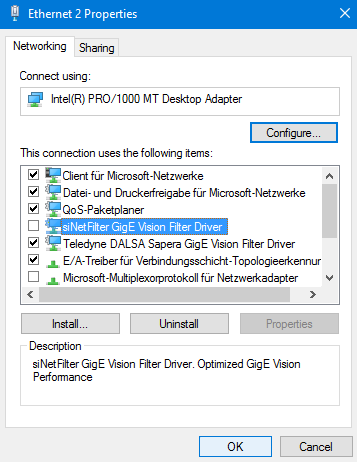
2) Uncheck the check box for the siNetFilter Driver.
3) Close all dialogs with the "OK" button to apply the changes.
When you disabled the siNetFilter Driver for a specific NIC you can enable it again.
1) Open you Network Properties Dialog (Start -> Control Panel -> Network Connections) right click on the network connection used. Select "Properties" from the context menu to get the network configuration dialog.
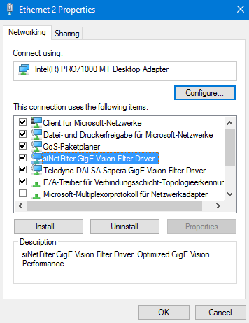
2) Check the check box for the siNetFilter Driver.
3) Close all dialogs with the "OK" button to apply the changes
To uninstall the siNetFilter Driver on all NICs follow these steps.
1) Open you Network Properties Dialog (Start -> Control Panel -> Network Connections) right click on the network connection used.
Select "Properties" from the context menu to get the network configuration dialog.
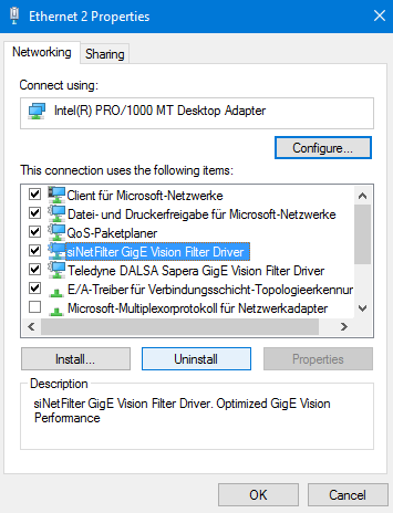
2) Select (not uncheck!) the siNetFilter Driver.
3) Press the Uninstall button and follow the instructions (it might be necessary to reboot the system afterwards).
4) Close all dialogs with the "OK" button to apply the changes.
USB3 Vision is a mere protocol or "on the wire" standard, based on USB3.0 standard using USB 3.0 ports. This means that only the data package layout and a bootstrap register map is defined. It ensures that a USB3 Vision device needs a certain "basic intelligence" without having to reload firmware. No manufacturer specific drivers will need to be installed on the host, provided that USB3 Vision compliant software is installed. USB3 Vision uses the GenICam GenApi device description for camera control. USB3 Vision defines a transport layer for:
Furthermore USB3 Vision provides an interface to GenICam.
USB 3.0 operates at a bandwidth of 5 Gbit/s enabling net data rates of substantially more than 350 MBytes/s.
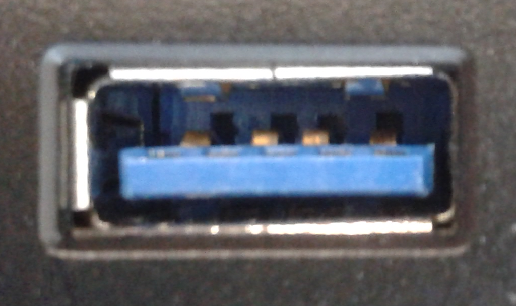
On Windows 8 and newer USB3 host controllers run using a Microsoft driver.
No vendor driver should be required.
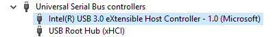
Renesas: Renesas also provides extension cards for USB3. The following drivers are required (unfortunately exact chipset is printed on the chip in super tiny letters)
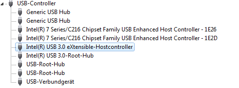
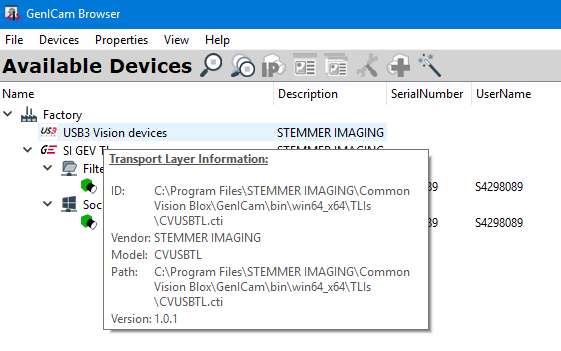
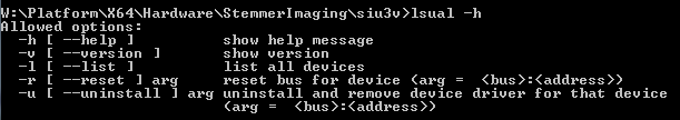
A typical output of lsual when a JAI USB GO is connected:
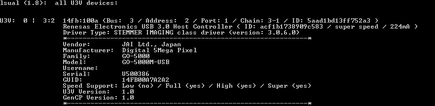
Most interesting parameter is the Speed Support: Super has to be supported.
Transport Layer are installed within the manufacturers software (SDK) setup for the frame grabbers and cameras. CVB driver packages for supported frame grabbers and cameras of different manufacturers are provided on the CVB download pages.
After installation drivers can be found under %CVB%Drivers. A CVB Camera Suite or Image Manager License releases the usage of those Transport Layer within Common Vision Blox.
Available Transport Layer are displayed in GenICam Browser:
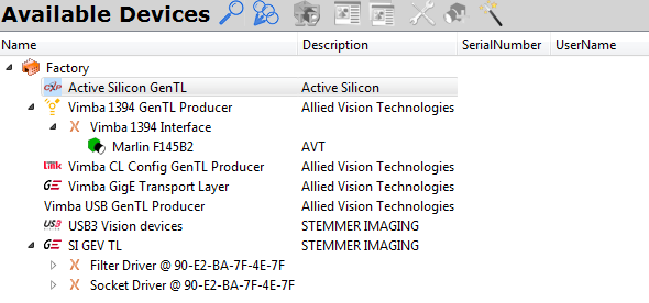
CVB GenICam Transport Layer (*.cti files) can be found for example under: %CVB%GenICam\bin\win64_x64\TLIs (Windows 64 Bit) or /opt/cvb/drivers/genicam (Linux)
Environment variable for GenICam TLs to find all *.cti files:
GENICAM_GENTL64_PATH
Windows (check with cmd shell command "set"):
Example CVB: C:\Program Files\STEMMER IMAGING\Common Vision Blox\GenICam\bin\win64_x64\TLIs
or %CVB%GenICam\bin\win64_x64\TLIs
Example other supplier, e.g. Allied Vision with Vimba or Active Silicon:
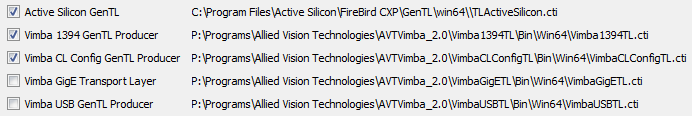
similar for 32 Bit system
Linux (check with cmd shell command "env"): GENICAM_GENTL64_PATH=/opt/cvb/drivers/genicam
Some functions (e.g.IP assignment) are available with CVB GenICam TLs only.
in GenICam Browser:
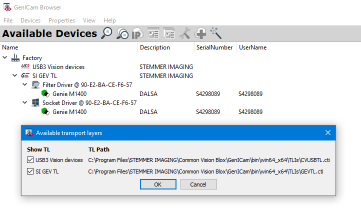
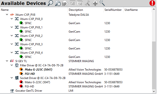
Registry-Entries: Registry entries affecting the use of Common Vision Blox drivers are located within the following key of the Windows registry.
in HKEY_LOCAL_MACHINE\Software\Common Vision Blox\Image Manager\...
CVB application problems caused by a foreign Transport Layer can be solved by renaming this from *.cti to any other name (e.g. *.cti.off).
This chapter provides information about supported programming interfaces and hints for the use of the CVB vin-driver with your image acquisition device. In general the programming hints refer to related detailed chapters in the section Image Manager.
 Please be aware that examples mentioned here are related to the newest CVB version, downloadable in the CVB user forum.
CVB provides a set of interfaces for all main features of an image acquisition device such as grab, software trigger, ringbuffer and much more grouped by functionality:
For general information on all CVB driver interfaces please refer the Common Vision Blox Manual - Image Manager chapter.
Supported interfaces to control a GenICam compliant device using the GenICam.vin are:
ICameraSelect2
IDeviceControl
IGrab2/IGrabber
IImageRect
INodeMapHandle/INodeMapHandle2
INotify
IRegPort
IRingBuffer
ISoftwareTrigger
Details regarding the supported interfaces with the CVB GenICam driver are presented on the next pages.
Mentioned Tutorials can be found in
%CVB%Tutorial directory (Windows) or
/opt/cvb/tutorial (Linux).
ICameraSelect2 Interface: switching between different devices
The ICameraSelect2 interface allows to switch between different connected cameras or image acquisition devices. The switching between devices is realized in CVB via the
A description of both possibilities can be found in the Common Vision Blox Manual. To test the basic functionality, please use the Common Vision Blox Viewer (button Show Grabber properties).
A platform independent C++ code example can be found in the MultiOSConsole example (Camera.cpp) of the Image Manager
Windows: %CVB%Tutorial\Image Manager\VC\VCMultiOSConsole
Linux: /opt/cvb/tutorial/ImageManager/ComplexMultiOSConsoleExample
IDeviceControl Interface: controlling hardware settings
The IDeviceControl interface offers the possibility to set or change hardware (i.e. camera) parameters directly over CVB.
The IDeviceControl Interface can be accessed through the CV Grabber Control or the Driver-DLL using:
Refer Common Vision Blox Manual Image Manager documentation for details.
Avaialble command values: The complete list can be found in the specific %CVB%Lib\iDC_*.h header file.
For example, the %CVB%Lib\iDC_GenICam.h for GenICam devices.
Often used command strings are listed here:
DC_BUFFER_INFO_TIMESTAMP: This is the time stamp received from the acquisition hardware saved to the acquired buffer in the memory.
DC_BUFFER_INFO_IMAGEID: This is the image id received from the acquisition hardware saved to the acquired buffer in the memory.
DC_BUFFER_INFO_NUM_PACKETS_MISSING: This is the number of missing packets from the image transfer of a GigE Vision camera related to the acquired image of the currently used buffer.
DC_BUFFER_INFO_DELIVERED_TRAILER_HEIGHT: This parameter is for variable image height. It can be used for LineScan cameras to know how many lines are valid in the buffer.
Command ID can be tested also over the Grabber Properties window in CVB Viewer or VC Sizable Display example in %CVB%Tutorial\Image Manager\VC.
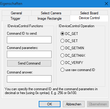
A description of the command types can be found in the Common Vision Blox Manual. To test the feature please use the CVB Image Manager Tutorial: VB Grabber OCX or one of the following examples:
VC++ Example Code: retrieve ImageID (from the VC++ GenICam Simple Demo)
VC++ Example Code: retrieve lost packets from last frame
VC++ Example Code: read the variable Image Height for Line Scan Cameras
IGrab2/IGrabber Interface: image acquisition
The IGrab2 interface was designed to do a continuous image acquisition into a image ring buffer and to be able to protect certain image buffers against overwriting. It provides functions for starting and stopping the acquisition, wait for an image, etc. All functions of this interface are also used by the CV Image Control if you start an acquisition by setting it's Grab property to TRUE. The function G2GetGrabStatus with its options* offers information about the image acquisition which can be used for monitoring and analysis.
Option examples:
G2INFO_NumPacketsReceived
This is related to GigE and indicates the number of data packets received on the GigE Vision streaming channel.
G2INFO_NumResends
This is related to GigE and indicates the number of resend requests issued by the host. If this number increases, it indicates that something is wrong with the data transmission. Possible reasons may be: Settings of the network card, CPU-load on the host, cable/switch problems, bandwidth problems on the Link.
The IGrabber interface is used for single image acquisition (snap). A detailed description of the interfaces can be found in the Common Vision Blox Manual.
A platform independent C++ code example is the MultiOSConsole example (Camera.cpp) of the Image Manager
Windows: %CVB%Tutorial\Image Manager\VC\VCMultiOSConsole
Linux: /opt/cvb/tutorial/ImageManager/ComplexMultiOSConsoleExample
This interface can be used to change the resolution of the image or to inform the driver for resolution changes made previously in the hardware.
Changing Resolution over IImageRect
For cameras allowing to read out a reduced size or parts of the image this can be used with the IImageRect Interface. The settings can be adjusted with the
Both approaches are documented in the Common Vision Blox Manual. For testing, please use the CVB Image Manager Tutorials.
Inform the driver about changed resolution or pixel format
With GenICam compliant cameras settings as resolution, pixel format and - if supported - binning or partial scan, can be changed in the camera directly. If one of these settings is changed, the image object has to be updated. You can restart the application or inform the driver about the changed resolution or pixel size. This is necessary as the underlying image object holds preinitialised buffers where the image stream from the camera is written to. When the size of the image changes the underlying image object need to be informed and the buffers need to be reinitialized.
To do that you need to:
C# Example Code:
For details regarding the IImageRect interface please refer to the description in the Common Vision Blox Manual.
This interface is used to obtain access to the GenICam NodeMap for the current device (e.g. a GigE Vision camera). INodeMapHandle is part of the Driver Library and provides functions to set and retrieve values from the NodeMap. A description of the INodeMapHandle functions can be found in the Common Vision Blox Manual.
Sample Code in C++ (CVB 2017 - 13.x.x)
Please see also the introduction of the INodeMap Interface in Common Vision Blox Manual. For testing purposes, please use the CVB GenICam Tutorial: VCSimpleDemo or CSGenICamExample (%CVB%Tutorial\Hardware\GenICam).
A GenTL exports a number of separate Nodemaps to access logical parts of the driver. Beside the well known device Nodemap a GenTL Producer provides a Nodemap to configure the Datastream and to get statistical data. Other technologies might as well have multiple Nodemaps. INodemapHandle2 allows to enumerate the various Nodempas and to get access.
INotify Interface description: callback functions for events
This interface allows to register callback functions for events like disconnect/reconnect or events generated by the device. In case such an event carries additional data, it is passed to the callback function. Refer also examples from Connection Monitoring chapter.
VC++ Example Code (CVB 2017 - 13.x.x):
C# Example Code (CVB 2017 - 13.x.x)
The IRegPort interface provides low level access to the current device. It is recommended that you use the high level interfaces e.g. handled by the CV GenICam Control. A description of this can be found in the Common Vision Blox Manual.
IRingbuffer Interface: image acquisition using ringbuffer
The ring buffer was designed to do a continuous acquisition into an image ring buffer. It protects image buffers against overwriting and can buffer several images if the following processing takes longer than the image acquisition for a short period of time. The ring buffer is used automatically with every CVB image acquisition and a default size of 3 buffers. It is recommend to use a value around the expected framerate so that a period of one second can be buffered. This can be modified in the option settings of the GenICam Browser.
The IRingbuffer interface can be used to modify the number of used buffers programmatic. It supports also other ring buffer modes. The access to the IRingbuffer interface can be done in CVB via the
ISoftwareTrigger Interface description - software controlled triggering
The ISoftwareTrigger interface permits the sending of a software controlled Trigger to the camera without any external trigger signal. To use the software trigger the camera or device has to be set to software trigger. The camera configuration can be customized with the GenICam Browser. In CVB the trigger feature is set with the
The documentation for both possibilities is available in the Common Vision Blox Manual.
A platform independent C++ code example can be found in the MultiOSConsole Example (Camera.cpp) of the Image Manager
Windows: %CVB%Tutorial\Image Manager\VC\VCMultiOSConsole
Linux: /opt/cvb/tutorial/ImageManager/ComplexMultiOSConsoleExample
Practical configuration examples can be found in the Use Cases - Trigger Configuration chapter of this manual.
With our GenICam architecture it is possible to be informed if a device disconnects or reconnects. This is called Connection Monitoring and is supported with GigE Vision.
This feature can be useful if a device temporarily loose its power and the connection needs to be re-established. The Connection Monitoring is realized over the INotify interface with its DEVICE_DISCONNECTED and DEVICE_RECONNECT event.
Important Notes:
Sample code how to use the INotify Interface for Connection Monitoring:
C++ Connection Monitoring Example (CVB 2017 - 13.x.x)
C# Connection Monitoring Example (CVB 2017 - 13.x.x)
If you want to access the GenICam camera parameters in your application, you have to retrieve the CVB NodeMap handle from the driver using theINodeMapHandle Interface. You can then pass this handle to the CV GenApi Grid Control or access the features using the functions of the GenICam Library. For details regarding the INodeMapHandle interface please refer to the description related to the Common Vision Blox Manual Image Manager chapter.
There are two different timestamps. One time stamp is output by the camera, independent of the image. The other time stamp is given by the camera when the camera acquires an image. Every acquired image gets a time stamp from the camera.
In the following paragraphs both timestamps and how to retrieve them will be explained.
Image time stamp - according to the acquired image
Camera time stamp - independent of the image
Purpose: This time stamp is used for example to archive images acquired together with the acquisition time.
There are different possibilities to retrieve the time stamp As a recommendation please use the IDeviceControl Interface of the CVB GenICam driver to retrieve the time stamp.
The favourite method is to retrieve the time stamp via the IDeviceControl interface supported by the GenICam.vin driver.
A) Using CVCDriver.dll
Please use the command DCBinaryCommand or DCStringCommand of the CVCDriver.dll to retrieve the time stamp as a 64 Bit long value. Especially for VB.Net DCStringCommand should be used. The command ID (0x800, DC_GET) must be sent to the driver. The value 800 must be given in hexadecimal.
B) CVB Grabber Control
Using the CV Grabber Control please call the method SendBinaryCommand (…) or SendStringCommand (…). The time stamp is retrieved as a hex String value and must be converted to a 64 bit value. For VB.Net the SendStringCommand must be used. The command ID (0x800, DC_GET) must be sent to the driver. The value 800 must be given in hexadecimal (see VB.Net Example below).
With the function G2GetGrabStatus (GRAB_INFO_TIMESTAMP ) of the CVCDriver.dll or the GetGrab2Status method of the CV Image Control the time stamp value can be retrieved as double value. Note that the internal time stamp is an int64 type which means that you loose accuracy when you retrieve the time stamp value with the IGrab2 Interface. For more accuracy of the time stamp value please use the IDeviceControl Interface for GenICam compliant devices.
Another possibility is to use the CV RingBuffer control and call the method GetTimestamp to retrieve the 64 bit time stamp value of type long, when the image is acquired by the camera.
Timestamps could be used to check if several cameras are running synchronously. But it is still possible that the timestamps can drift apart. The “TimestampControlReset” must be pressed to check for synchronous acquisition. Through this timestamp it can be monitored, if the camera is running synchronously to the time of the PC.
For retrieving the timestamp the Common Vision Blox GenICam API (Library or Control)must be used.
Retrieving the timestamp from a GenICam compliant camera may work as the following:
Screenshot of the GeniCam property grid showing the mentionend features (consider possible parameter name variance):
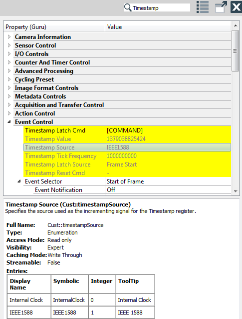
VB.Net Example: Using the GenICam Library
This example shows how to retrieve the different parameters (mentioned above) for the time stamp evaluation from the Nodemap of the camera.
Example programs with source code for all supported API's using the GenICam Driver, the GenICam Library and the CV GenApi Grid Control are installed with the setup and
are also available within Common Vision Blox API Overview. They are available via the
For GenICam it is recommended to use the CSGenICamExample, VCGenICamGrabConsoleExample or the CSGrabConsole example as reference. A platform independent example for Windows and Linux is the VCMultiOSConsole tutorial.
However, you can also use all other examples loading the GenICam.vin driver and connecting GenICam compliant devices.
A detailed description of the CVB Tutorials can be found in the Common Vision Blox Manual.
Find the Release Notes with vin-driver versions online under Version History or refer to the Common Vision Blox Release Notes (also located in your start menu and in the doc sub-directory of your Common Vision Blox installation).
Basic definitions
GigE Vision FAQ
USB3 Vision FAQ
Also refer CVB user forum.
What is GenICam?
Where do I get the GenICam spec?
Where do I get the Vision Standard specifications?
Can GenICam be applied to other interfaces like Firewire or USB2?
If something is GenICam compliant does it need to be GigE Vision Compliant?
The target of GenICam is to provide complete plug & play functionality for imaging applications. Every GenICam camera contains a GenAPI XML description that lists the available camera features. In this way, different cameras with different features can be addressed via the same software interface without any problem. So it allows 3rd party software like CVB to implement a generic software interface. For more information please look at www.genicam.org.
GenICam is hosted by the EMVA ( European Machine Vision Association ). Further info can be found under www.genicam.org.
The Vision Standards are maintained and owned by the Automated Imaging Association ( AIA ). Since they own the right we can not simply give it away. Refer the www.automate.org for following standards:
CoaXPress is hosted by the Japan Industrial Imaging Association (JIIA), see www.jiia.org.
The goal of the GenICam design was to support not only GigE Vision but also IEEE-1394 as well. GenICam can also be used to control any other kind of device such USB, but since there is no real standard for these technologies it really is up to the manufacturer to make sure the devices work with GenICam.
Some people say that GenICam is the compatibility layer. A device which is GigE Vision compliant must also be GenICam compliant since GigE Vision has a mandatory reference to GenICam. This is not the case in reverse however, since GenICam can also be used on other technologies. It therefore can not have a fixed reference to GigE Vision.
What's the difference between GigE and GigE Vision?
Is there a reference implementation for GigE?
How about 10 GigE?
What is DHCP?
What is LLA?
What is a NIC?
What is a filter driver?
Is it possible to use wireless networks to transfer my image data?
Is it possible to use Multicast with GigE Vision?
Is GigE Vision IPv6 ready?
Why do I need to spend money on a switch or on a network card?
I'm trying to select a switch. What are the parameters I should look for?
Can I connect more than one camera per network interface?
Why doesn't GEV use QOS (quality of service) to control the flow of data?
What's the CPU load caused by GigE Vision?
Can I use my laptop?
What is the maximum performance of one GigE NIC?
What is the data latency compared to a frame grabber?
What is the round trip time on a GEV setup?
What do I have to know if I want to use a fibre connection?
UDP is a "not reliable" protocol. Why is UDP used?
How fast is the control protocol?
Can I use Fast Ethernet or 10MBit connections?
Is power over Ethernet available for GEV cameras?
Is there a Linux implementation for GEV?
What cable do I need?
Is a Gig E Vision connection robust?
What happens if a packet gets lost? Does the application get notified when the data is corrupt and can it do a resend. What latency can this cause?
What happens if the network fails?
How does GigE Vision recover if the network fails? Does it need to be reinitialized?
Is GigE Vision applicable to just cameras or could it be used for vision related peripherals like Lighting and timing controllers?
Can a GigE Vision device be simulated in software to enable fast data transfer between different computers?
Can I use multiple filter drivers for one NIC?
Can I change the order in which the filter driver is placed into the driver stack?
Can I use network analyzer software on my GigE Vision system?
Can I use software VPN on my GigE Vision system?
Which software packages are known to cause problems on a GigE Vision system and how can I solve those problems?
Can I optimize my network card for GigE Vision?
I can adjust the size of the receive descriptor list on my NIC. What does that mean?
I can adjust the interrupt rate on my NIC. What does that mean?
Which network ports are used by GigE Vision?
GigE means Gigabit Ethernet and is the general Ethernet network technology combined with the bandwidth specification Gigabit. GigE Vision (GEV) is the name of a network protocol, optimized for machine vision, maintained by the AIA (Automated Imaging Association) designed to control machine vision devices (cameras) and to transfer their data (images) as effectively as possible across IP networks. Although GigE Vision contains GigE in its name, the protocol also works on lower bandwidth, although at least GigE is recommended.
No, there is no reference implementation. The standard is available only as a PDF Document. GEV products are bound to a self certification process. Compliance test software will be available however.
The protocol used on 10 GigE is no different to the one used on slower connections. Therefore, 10GigE should simply just work. The only problem might be the performance. You can not simply multiply it by 10 since you will reach the limitations of the PC. The other factor is the cost, since 10GigE is still a little expensive. To get exact numbers we would have to investigate and that has not yet been done.
DHCP (Dynamic Host Configuration Protocol) is a protocol which allows a device on the network to request a free (not used by another device) IP address from a DHCP server. See https://en.wikipedia.org/wiki/DHCP.
If a device is configured to use DHCP but can not find a DHCP server it will, after a certain time, automatically fall back to a mode called linked local address (LLA). On IPv4 networks (which is what we usually have) that means that the device assigns itself an IP in the range 169.254.x.x where the x.x are picked randomly with a subnet mask 255.255.0.0. It then tries to broadcast to the network to find out it that IP is already taken. If the IP is free, it will be used. If it is already taken, another address will be tried (https://en.wikipedia.org/wiki/Link-local_address). IP V4 address range for LLA is 169.254.1.0 through 169.254.254.255 according to RFC 3927.
A NIC is a "network interface card". This does not really mean the card itself but a single network connector. So, for example, if you have a motherboard with 2 on board GigE interfaces (2x RJ45) you have two NICs in your system. If you have a multi port network card each RJ45 (that is the name of a well known ethernet connector) on that multi port card (max. known is a 4 port card from Intel) is referred to as a separate NIC.
A filter driver is a kernel-mode driver which normally resides between the upper-level protocol and the lower-level miniport drivers (on a Windows based system). For GigE Vision technology it is used to bypass the standard network stack (used by the operating system) for all data stream packets. It filters GigE Vision related data packets and transfers them directly to an application-provided data buffer. This greatly reduces the CPU load of the system. All non GigE Vision data stream related packets are unaffected.
In principle there is no problem running a GEV camera over a wireless connection. The problem here is one of reliability. Wireless networks dynamically adjust their speed depending on the connection quality. This means that if the connection quality suddenly drops for some reason, a lot of packets will be dropped on the network. This leads to an avalanche of resend requests from the host (which did not receive the packets) and in the worst case scenario, this will cause the whole connection to the camera to fail. So, in principle, yes it will work but it is neither guaranteed or recommended.
The short answer is YES. The long answer is: Multicast is a Layer 3 IP protocol implementation. GEV is on Layer 4 so in general GEV will simply use the different IPs associated with Multicast ranges. The question is, whether the hardware (switches) and the software you are using supports it. CVB did not support Multicast from the first version on but in further releases. Please refer to the actual specific GenICam Driver Release Notes.
It is prepared but not yet implemented. All points where IPs are stored in the device are prepared but are not part of the current standard.
There are big performance differences between different network cards from different vendors (driver performance, on-board memory etc.). We prefer Intel for the network card given the choice. For switches it is a bit more complicated and we need to evaluate certain features on a case by case basis. Just because a product says ‘Gigabit Ethernet’ it does not guarantee that is provides the best performance.
Firstly it is important to say that it can be very hard to get the required information on a specific switch. There are no fixed expressions or specific numbers. So one vendor might call it xxx and the other yyy. We only can give you descriptions that relate to technical behavior.
In general: If you cannot find a specific value in the documentation you can always contact the manufacturer to get the information directly or you might simply assume that this switch is not good enough in this aspect because the vendor has attempted to hide it.
| Switching Bandwidth: | Is the overall bandwidth a switch can handle across all ports |
| Max packet rate: | Max number of packets per second across all ports. |
| Jumbo Packets: | Maximal packet size possible. With the growing size of packets we get less overhead and better performance on the transmission. |
| Layer 2 / Layer 3: | You need Layer 3 switches if you need multicast. Otherwise it is not that important. |
| Memory for packet storage: | If you have multiple cameras connected to a switch and one gigabit link to the host you might end up with a peak bandwidth above one gigabit. In this case a switch with memory can buffer the packets and send them out with a small delay. |
| SFP slots: | If you need to run your network across fibre instead of copper most switches don’t have direct fibre ports but little slots where you can plug-in a little stick called SFP (small form factor pluggable) which holds the actual fibre connection. These SFP add to the cost of the system because they are not included in the price of the switch. |
| Number of Ports: | Is the actual number of cables/fibres and therefore devices you can connect to your switch. Watch out - sometimes, if you have SFP-Slots in your switch they share a ports with a copper RJ45. So for example: we have a 12 Port Netgear GigE switch in our portfolio. It has 12 RJ45 copper connectors and 12 SFP slots. That means that every RJ45 shares a port with an SFP-Slot and you can only use either, not both, ports. |
| Managed switches: | Most managed switches allow you to configure one of the ports as a monitoring port. That means that all packet traffic is mirrored on this port, which can help when debugging potential problems. This also manages switches, and maintains an error log which again helps to detect network cable problems. |
Vendors are:
Yes, the number of cameras that can be connected to a single NIC is not limited in practice. So it really depends on bandwidth and latency, and hence no general answer. The more cameras you connect the more you have to think about peak bandwidth and latency.
One reason is that QOS with IPv4 is cooperative between the connected devices. It is not necessarily reliable or even forced as it is with other technologies. This might change in Ipv6 once that is supported. The other problem with QOS is that one cannot really predict the bandwidth that a triggered camera might use. There might be a peak bandwidth of 1 gpps one moment, while in the next second there might be no transfer for one minute! Also, with GigE you are not limited to a specific number of cameras you can connect. You could have 100 cameras all triggered at the same time but only once per minute. How would you share their bandwidth? What has been implemented however is a mechanism called inter-packet delay. This puts a small delay between the sending of packets which enables you to limit the bandwidth of a single camera and leave it to the switch to buffer and serialize the data from multiple cameras.
This really depends on the system you use, the bandwidth of the camera, the packet size, the driver software and the performance of your network components. The new multi-core CPUs are ideal for GEV because the operating system can distribute the load among them.
Yes, but bear in mind that a Laptop might not have the same performance as a desktop system. It mainly depends on the CPU and on the connection between the NIC and the memory. There are machines out there which use PCIe which has a better performance then PCI. The worst scenario would be a connection via PCMCIA.
Depending on your system configuration you can stream above 100MB/s sustained through one NIC. That does not mean that you can easily extrapolate this to two, three or four NICs. If you have applications close to that limit it is recommended that you contact the technical support of STEMMER IMAGING respectively your local distributor.
The short answer is: That depends on the system. The long answer is more difficult. It really depends on the camera in use, the network setup, the packet size, the PC and the system load. Assuming the camera is connected directly (no switch or router, no lost packets on the network) and with almost no CPU load on the receiving system, the latency is in the µs region. Every switch would add to that (again depending on the switch) probably in the lower µs range. But all this is a simple delay and is relatively easy to handle since it is the same with every image. The worst situation is a jitter in the arrival of images depending on the transmission quality and on the system load. If you have to perform a resend with a GigE camera, this adds to the data latency which is not predictable.
To measure a roundtrip time we used a camera which indicated the end of frame transfer in the camera by a digital output signal. We triggered an image in the camera and as soon as the application reviewed the complete image it set another digital output signal in the camera. We measured the delay between the two signals with an oscilloscope. Once again, the time depends on various factors. We measured a roundtrip time of about 3.5 ms. This gives a realistic estimation on what such a delay would be in a real application.
The biggest difference here is selecting and handling the fibre itself. There are a number of different connectors available, different fibres and different wavelength etc. But all this relates to the physical layer, not to GEV. For GEV there is NO difference between using a fibre connection or copper. If you need help setting up a fibre connection and/or choosing the right components please contact the technical support of STEMMER IMAGING respectively your local distributor.
That is true, but this is the reason why we have GEV. Since UDP is a connectionless protocol and since it does not have mechanisms to cope with lost packages we put a protocol layer on top so that we take care of these weaknesses while still maintaining the optimal performance at the lowest possible integration costs. We chose UDP instead of TCP because of performance and cost reasons.
See also FAQ Is a Gig E Vision connection robust?
On an average system it takes between 0.5 ms and 2 ms (depending on the device and the network setup) to write a GEV register from the issue of the Write Reg command until the PC has the acknowledge. This timing is for a direct link.
Apart from the limited bandwidth, GEV cameras should work just fine on Fast Ethernet (100MBit) or Ethernet (10MBit). The only problem might occur if the link on the camera is 1GBit to a switch and then 10MBit or 100MBit from the switch to the host. In that case the camera does not know about the limited connection and will send the packets at full Gigabit speed. The switch can not forward that bandwidth and will drop packets. The host will see the missing packets and request resending. For such a setup you have to limit the bandwidth of the camera or use a switch with internal memory to temporarily buffer the packets.
No, not yet, due to the size of the components and their limited power. There might be products in the future.
That is dependant on your software vendor.
GigE specifies Cat5e cabling, but to be on the safe side we recommend Cat6 cables which have better shielding. Cat7 cables are available for higher frequencies but as yet there are no connectors defined.
The short answer would have to be yes.
The long answer would need to explain why this is the case since a UDP base protocol like GigE Vision sits on top of a Gigabit ethernet connection which is is not reliable as such. With UDP we face two major problems. The first is that UDP is not connection oriented so we need to have a mechanism that enables each end to check that the other end is still available. The 2nd problem is lost packets due to a number of different reasons.
So to solve the connection question, GigE Vision implements a mechanism called Heartbeat. This enables the camera to determine whether the host is still up and running. The other problem is covered by the control protocol.
The packet loss is handled in different ways. With the control protocol, a lost package is detected by a ‘send and acknowledge’ mechanism. The streaming, in order to achieve better performance, works with a different method. Each data packet has a unique id so that the receiving host can identify missing packets and send a resend request to the device ‘on-demand’. The device will store a certain number of packets and on receiving such a request it will resend the data.
This solution, in combination with a CRC (checksum) makes GigE to the most robust transfer technology we have so far in Machine Vision. With CameraLink there is no possibility of identifying corrupt data, e.g. flipped bits due to too long cables. With 1394 on the other hand we can also identify corrupt packets but don't have such a resend mechanism. So without enumerating all technologies in this document, GigE Vision is as reliable as it can be.
On the other hand there will be a higher data latency which will be added to the data transfer and camera control when something goes wrong. And it is even worse, because we can not deterministically predict these latencies when we assume that a control protocol packet gets lost, the camera sends no acknowledgement. The host will wait a certain time until a timeout arrives and resend that command. This time the packet might get through, but the acknowledgement now get's lost. Finally the third attempt works. This, of course, would be on a very very bad connection but this could happen. So the comfort of having a safe connection brings a less deterministic behavior timewise. How much this impacts the performance, really depends on the connection you are using, the components involved and the load on the host. If nothing goes wrong and the connection does not loose packets we have NO performance loss.
Please also refer to the following FAQ's:
See FAQ Is a Gig E Vision connection robust?.
That really depends on the network topology. In general, if the network fails, the application will know about it and it try to reestablish the connection.
If the network fails the device and the host will loose the link and will disconnect. Common Vision Blox (CVB) fires an CVCError-event announcing an Acquisition Error . Then the GenICam Driver has to be reloaded.
Devices which don't need to stream data can simply use the control protocol only and not expose a streaming channel. In this way GigE Vision can be used as a simple control protocol.
Yes of course it can. Since GigE Vision uses standard network protocol mechanisms it can be implemented in software on the host.
You can use more than one filter driver for one NIC e.g. if you have SDK's or GigE Vision devices from several vendors on a single system. The maximum number of filter drivers for one NIC is limited. There is one major drawback using multiple filter drivers on a single NIC. Assume you have installed 2 filter drivers from 2 different vendors. You have a GigE Vision device from each vendor which is processed by the filter driver of that vendor.
Your network stack will normally look something like this:
PROTOCOLDRIVER (upper-level)
FILTERDRIVER_B
FILTERDRIVER_A
MINIPORTDRIVER (lower-level)
NIC
Device_A + Device_B
All data stream packets from Device_A are filtered in FILTERDRIVER_A.
All data stream packets from Device_B are filtered in FILTERDRIVER_B.
But all data stream packets from Device_B have to pass FILTERDRIVER_A before they are processed by FILTERDRIVER_B.
This will cause additional CPU load. The more drivers you have in the stack the more CPU load you will get. You can use different filter drivers on different NIC's. without causing additional CPU load when you disable (not uninstall) the unused driver for this NIC.
No you can not. This is controlled by the operating system. You can not select which driver is lower or higher in the stack.
You should not. If you use a network analyzer software like Wireshark on your GigE Vision system you might run into problems. Wireshark for example uses the WinPCap kernel mode protocol driver to analyze all incoming and outgoing packets. Depending on the order in which the operating system has installed the filter drivers and WinPCap in the network stack, your filter driver might not receive any GigE Vision data stream packet. In that case you will get no GigE Vision data!
You should not. We have seen problems e.g. using VPN software from Cisco. There are similar reasons for this as mentioned under FAQ Can I use network analyzer software on my GigE Vision system?
VPN Software e.g.: Cisco VPN (Solution: disable network service called Deterministic Network Enhancer + Stop VPN service with "net stop cvpnd") Network Analyzing Software like Wireshark (Solution: uninstall WinPCap)
See also FAQ's Can I use network analyzer software on my GigE Vision system? and Can I use software VPN on my GigE Vision system?
Yes you can. The optimization depends on the hardware you are using. So bear in mind that you should always use the proper hardware.
Please have a look at our recommendations for the Performance Settings.
This sets the number of buffers used by the NIC driver that are used to copy data to the system memory (normally done with DMA). Increasing this value can enhance receive performance, but also consumes system memory. Receive descriptors are data segments that enable the adapter to allocate received packets to memory. Each received packet requires one receive descriptor, and each descriptor uses certain amount of memory (e.g. 2kB for a INTEL Pro/1000). If the number of receive descriptors is to low than the NIC might run out of memory which will cause packet loss. For GigE Vision this might cause a lot of packet resend requests.
Depending on the NIC you are using, you can decrease the number of interrupts generated by the NIC. This has some influence on the CPU load. On a INTEL Pro/1000 card you can decrease the number of interrupts that are generated by setting the "Interrupt Moderation Rate" to "Extreme". For other network cards there are similar ways of decreasing the interrupt rate.
GigE Vision consists of a control and a streaming part. Only the control connection is claiming a static port on the device end (UDP 3956), which is also registered with IANA. The control connection source port as well as the streaming connection port(s) are dynamically allocated from the ephemeral port range 49152 through 65536.
USB3 Vision is a machine vision standard, maintained by the AIA (Automated Imaging Association), designed to control machine vision devices (cameras) and to transfer their data (images) as effectively as possible across USB3.0 interfaces.
CVB supports every “USB3 Vision” camera, as it implements the USB3 Vision standard, please note that “Vision” is important, as there are USB3 cameras on the market which do not follow the standard is not a USB3 Vision camera - the GenICam.vin driver will not work with this camera and you have to use the extra drivers for the camera (e.g. CVB IDS Driver for IDS USB cameras). Is there a reference implementation for USB3 Vision? No, there is no reference implementation. The standard is available only as a PDF Document.
Yes, because Sherlock can be used with any image source supported by CVB it will also support USB3 Vison cameras.
Documentation
Please also take a look at the specific camera manual supplied by the manufacturer.
The CVB related documentation for the CVB Driver is available via the Start menu entry STEMMER IMAGING-Common Vision Blox-Documentation-Hardware-GenICam.
Further documentation can be found in the Common Vision Blox Manual. More detailed hints and information regarding hardware and software configuration of GenICam Devices under CVB can be found in
Updates
Please check the CVB Web pages for updates to this driver in form of a CVB service pack or a hotfix. Therefore please visit the CVB User Forum Download area and choose the CVB Version or Operating System and navigate to the section List of available Updates. For any kind of problem you encounter it is very helpful to record the error logging of the CVB GeniCam driver. Please have a look at the description of the Error logging.
Technical Support
Before contacting the Technical Support please review the
Report the versions of Common Vision Blox, Operating System and the devices serial numbers. Use the support contact form.
The license options are described in the CVB Manual. Complete License Management is to be handled with License Manager. If there is a CVB watermark in the Device View/Video interface following reasons are possible.
| - The license entry is missing. Camera Suite License covers GigE and USB3 vision Transport Layer. - The license entry does not cover the actual Transport Layer usage. For other Transport Layer integration an Image Manager License is needed. |
For GigE Vision or USB3 Vision devices in the GenICam Browser the License key can be retrieved for available devices using the Retrieve License key. The browser has to be started as Administrator or Root before.
Through MAC address/USB serial number of the camera you will immediately receive the appropriate licence key for the CVB CameraSuite license.
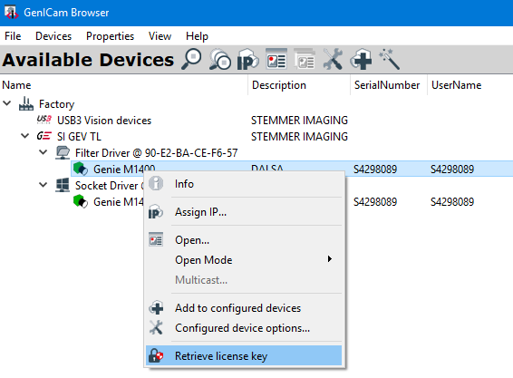
If you connect a USB 3 Vision Device Windows is searching for the best fitting driver for this device. If CVB is installed and no other driver is available which supersedes the CVB ones then it is installed and the device should work. But if Windows choose the wrong driver we need to uninstall the other driver with the Windows Device Manager. Then the driver will be used.
Within Linux there is normally one USB3 Driver. And this driver should work for all. Otherwise there is no output from lsual.
In the folder %CVB%\Hardware\StemmerImaging\Utilities: Use “lsual –l” in a console window.
The chipset driver might also be too old. Please install the newest available driver for your chipset. Refer USB3 Vision System Requirements.
For this camera an external power supply through the 12-pin Hirose connector is essential.
The camera is not seen in the GenICam Browser/GenICam Device Configurator
I can open the camera in the GenICam Browser/GenICam Device Configurator but get a white picture
I can open the camera in the GenICam Browser/GenICam Device Configurator but get a flickering picture
Image contains a logo or is complete grey
Error message: Nodemap unavailable
The CVB pixel type is wrong
I get a large number of lost frames
The acquired images show defects
I can acquire images but the GigEVision events from the camera are not fired
GigE Cameras disappear in the GenICam Browser
Occasionally Time Out errors when performing image acquisition with Software Trigger
How can I enable Packet Resend in the driver?
How can I discard corrupt frames in the driver?
How can I find the installed transport layer ?
For GigE Vision make sure the IP addresses of both the camera and the NIC the camera is connected to, are on the same subnet,if you have multiple NIC's in the system make sure they don’t share the same subnet's. Otherwise this can result in unpredictable behavior. Refer GigE Vision checklist.
For USB3 Vision please ensure that USB 3.0 ports are used and all other hardware requirements are fulfilled. Refer USB3 checklist. Seldom it could be necessary to delete the GenIcam XML file and directory manually: %CVBDATA%GenICam and start the application again. For all other vision hardware components (cameras, grabber) ensure that the necessary software and driver is installed.
Change the Display Engine type from OpenGL to Raster. Display Engine can be changed only if no device is open. If the selection is disabled, all devices must be closed.
This can occur with high performance cameras or multi-camera scenarios which are producing pictures with a higher bandwith than the communication link is able to transfer (GigE Vision, USB3 Vision).
Cameras transfers empty pictures as soon as a bottleneck is detected. This can be observed with the flickering effect on freerun pictures in CVB and watching the Data Stream Port statistic values. Exposure time adaption, Framerate decreasing to a value matching the transfer capabilities and optimizing the network configuration for GigE hardware should solve the problem.
If the cameras are not licensed via CameraSuite or any other valid Image Manager license like a dongle, a Node-locked or Triallicense there are sent some kind of distorted images. This could be either a logo as a watermark in the left top part of the image:

or that grey images with a grey value of 128 appear from time to time. Additional there appears a red text overlay in the display which says " Common Vision Blox evaluation".
If the device has no XML file in its memory "Nodemap unavailable" message is returned when a device is opened. Be aware that setting a correct XML file for the device is a precondition - so it has to be (re)generated. Availability, version and binding information of a camera GenICam XML-file can be checked with the EditBindings application. Sometimes it could be necessary to backup and delete the GenIcam XML file and directory manually: %CVBDATA%GenICam and start the application again.
Check or change the pixel format setting with the GenICam Device Configurator - Device Settings. Please refer to the Common Vision Blox Manual for more details.
Check the hardware components and configuration if they inter-work with the camera configuration and capability. Most problems are caused due to unsatisfactory performance.
If sections of the acquired images are missing or random noise is visible, the reason is probably a transmission problem. The following image shows an example of this type of transmission problems:
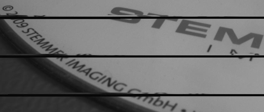
Maybe you see black lines or lines with old image data. Check the hardware components and configuration if they inter-work with the camera configuration and capability. Please refer the corresponding chapters in this User Guide for optimization.
Disable the firewall. Enable the events with the EventNotification feature.
The system was already working and without changing anything the GigE camera does not appear any more in the GenICam Browser. But it is possible to PING the camera. Means IP configuration and camera is OK. Solution: Please delete the following file in the CVB Root path ..\Genicam\Registry\xml\db.xml Restart the CVB GenICam Browser and you should see the GigE camera again connected.
This problem may occur mainly on cameras with high data rate. Check the hardware components and configuration if they inter-work with the camera configuration and capability. Please refer the corresponding chapters in this User Guide for optimization.
By default packet resend is disabled in the driver. To activate it you need access to the DataStream Nodemap of the driver. In the NodeMaps section you can read how to access the DataStream Nodemap. There is also an example in C++ how to enable the Packet Resend.
By default corrupt frames are passed thrue the driver. You can disable pass corrupt frames with the DataStream Nodemap of the driver. In the NodeMaps section you can read how to access the DataStream Nodemap. There is also an example in C++ how to discard corrupt frames.
Transport Layer environment variable: GENICAM_GENTL64_PATH to find all *.cti files
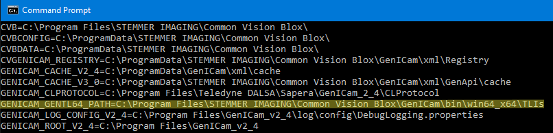
In GenICam Browser: Properties > Options > Save Properties > Select All:
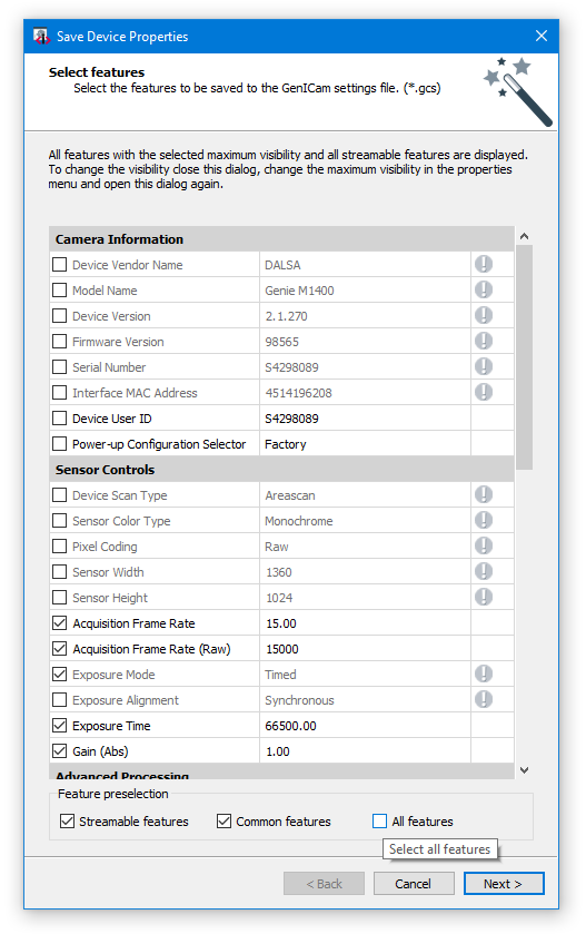
In GenICam Browser Logging window the log data can be saved as *.log file.
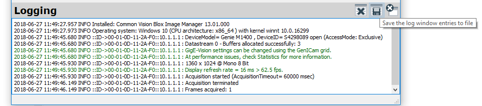
GenICam Browser offers Statistic values since CVB 2017:
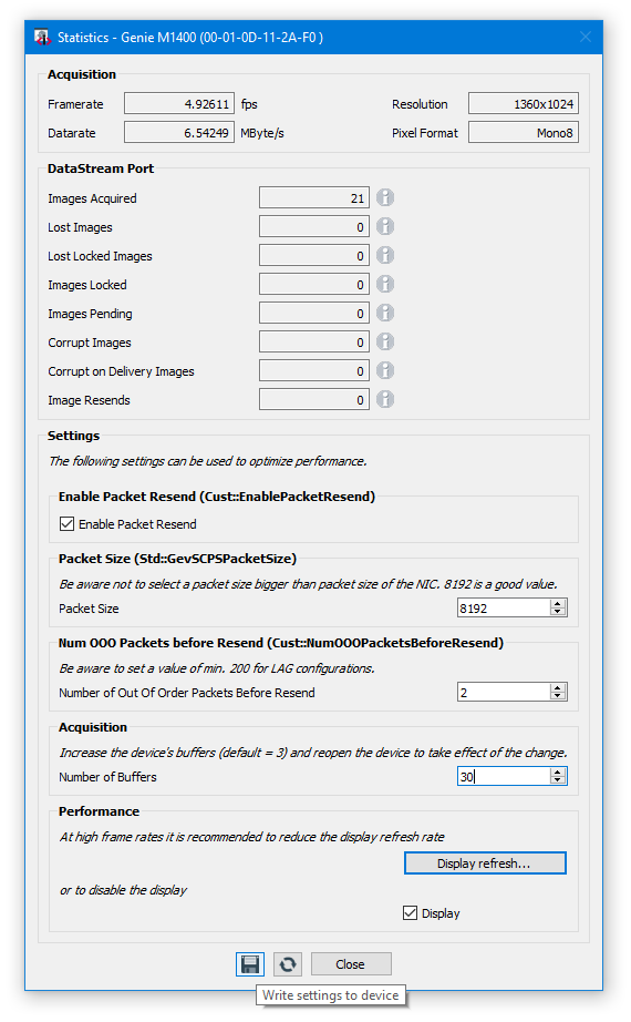
CVB Viewer gives you also the possibility to see acquisition statistics about transfer and lost images.
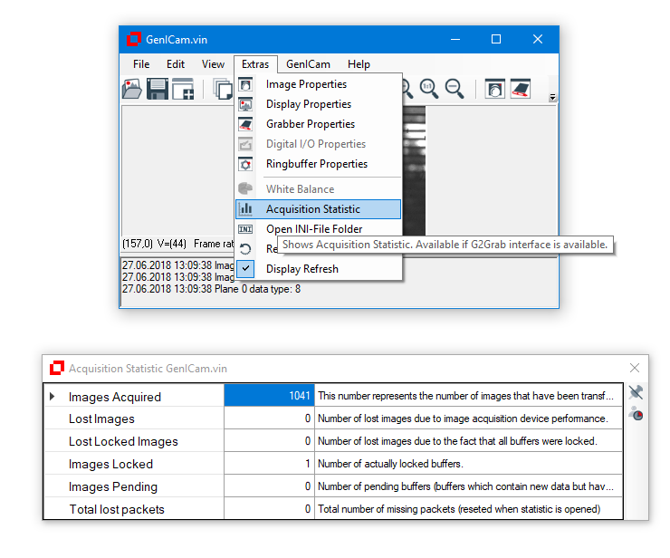
Also the FramesCorrupt parameter at the Nodemap Stream Port can be monitored:
Number of images which were corrupt on arrival in the host no matter if or if not resend requests have been issued. This setting indicates if something is wrong with the transmission. A corrupt image is an image which in the first run did not arrive properly and points to transmission problems caused by bandwith limitations.
Since CVB 2017 the LogGUI application LogGUI.exe can be used for logging: %cvb%Applications
For all other versions before follow following steps:
Windows:
1) Create Environment Variable CVBLOG=%CVBDATA%\log
2) Create Folder %CVBDATA%\log
3) Load Driver once and three *.json files are created
4) Now you can activate the logging in every json file for the corresponding module
e.g. To activate the logging for the GenICam.vin driver open the GenICamVIN.log.config.json and change "destination" and "level" like this:
{
"log":
{
"destination": "console",
"destination_option_0": "none",
"destination_option_1": "file",
"destination_option_2": "console",
"destination_option_3": "trace",
"destination_option_4": "service",
"file":
{
"name": "C:\\Temp\\GenICamVIN.log"
},
"level": "0xFF",
"level_option":
"none": "0",
"info": "0x0F",
"warn": "0x07",
"err": "0x03",
"fatal": "0x01",
"debug": "0x3F",
"trace": "0x1F",
"all": "0xFF"
}
}
}
If "destination": "file", is used the "name": has to have an absolute path to where you want to safe the log file. Please note that you have to use either "\\" or "/" as the separator in the path to the logging file.
1) You can choose a different target folder if you want. But the target folder in the environment variable has to be created manually
2) GenICamVIN.log.config.json: logging from the GenICam.vin driver
3) GEVSD.log.config.json: logging from the socket driver
4) GevTL.log.config.json: logging from the STEMMER IMAGING GigE Vision Transport Layer
5) USBTL.log.config.json: logging from the STEMMER IMAGING USB 3 Vision Transport Layer
Linux -Debugging
Run GenICam Browser with flag –debug. This will generate a Debug.log in the same directory. Within /opt/cvb/bin you have to run debugging with sudo. Or you make a symbolic link to GenICamBrowser to your home directory.
Then you can run it without sudo:
In your home directory: ln –s /opt/cvb/bin/GenICamBrowser GenICamBrowser