|
|
Foundation (OpticalFlow.dll) 14.0
|
|
|
Foundation (OpticalFlow.dll) 14.0
|
Functions | |
| cvbbool_t | OptFlowColorOverlay (const OPTICALFLOW opticalFlow, IMG cvbImage, double alpha) |
| Creates a visualization of a motion vector field by painting color-coded motion arrows into a copy of the most recent reference image. More... | |
| cvbbool_t | OptFlowVectorOverlay (const OPTICALFLOW opticalFlow, IMG cvbImage, double alpha, double lengthFactor, cvbbool_t fixedLength, cvbbool_t antiAliasing) |
| This function displays the motion vectors as a overlay of transparent arrows on top of a monochrome copy of the most recent reference image. More... | |
| cvbbool_t OptFlowColorOverlay | ( | const OPTICALFLOW | opticalFlow, |
| IMG | cvbImage, | ||
| double | alpha | ||
| ) |
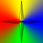
Creates a visualization of a motion vector field by painting color-coded motion arrows into a copy of the most recent reference image.
The motion arrows painted by this function are color-coded as follows:
Neither the results of optical flow calculation, nor the reference image need to be submitted explicitly to this function. Instead, they are being extracted from the opticalFlow handle. The color overlay image will be written to a compatible CVB image object, which can be created by means of the function OptFlowCreateCompatibleImg.
If the reference image was submitted as a color image to OptFlowCalculate or OptFlowCalculateSeq, the pixels will be automatically converted to monochrome values.
Please note that the generation of this visualization has a notable influence on overall performance and it is not uncommon for the generation of the visualization to take long than the actual computation of the motion vector field. This applies to both visualization function but is particularly true for OptFlowVectorOverlay.
latticeSpacing is not too big or if the results for pixels between lattice points are obtained by interpolation. In other cases, i.e., choosing interpolation = OFI_None, the visibility of the color overlay might not be sufficient if the lattice points are far apart from each other.| [in] | opticalFlow | Valid CVB Optical Flow handle as created by OptFlowCreate. |
| [in] | cvbImage | Destination image object handle. This image needs to have the same size as specified during the creation of the opticalFlow handle. It needs to refer to an image with 8 bits per pixel and component and the pixels need to be arranged in an interleaved ARGB layout. The easiest way to create such an image is though a call to OptFlowCreateCompatibleImg.After a successful function call, cvbImage will contain the (optionally transparent) color coded overlay of the motion vector directions on top of the monochrome reference image currently stored in the opticalFlow handle. |
| [in] | alpha | Controls the transparency of the color overlay. If alpha = 0.0, the overlay color of the vectors' direction is completely transparent and thus not visible. If alpha = 1.0, the overlay color is completely opaque and the underlying monochrome values of the reference image are not visible. Acceptable values: |
TRUE on success, FALSE on failure (in this case an error message can be retrieved with OptFlowGetErrorMessage). | cvbbool_t OptFlowVectorOverlay | ( | const OPTICALFLOW | opticalFlow, |
| IMG | cvbImage, | ||
| double | alpha, | ||
| double | lengthFactor, | ||
| cvbbool_t | fixedLength, | ||
| cvbbool_t | antiAliasing | ||
| ) |
This function displays the motion vectors as a overlay of transparent arrows on top of a monochrome copy of the most recent reference image.
The motion arrows painted by this function are color-coded as follows:
Neither the results of optical flow calculation, nor the reference image need to be submitted explicitly to this function. Instead, they are being extracted from the opticalFlow handle. The color overlay image will be written to a compatible CVB image object, which can be created by means of the function OptFlowCreateCompatibleImg.
If the reference image was submitted as a color image to OptFlowCalculate or OptFlowCalculateSeq, the pixels will be automatically converted to monochrome values.
Please note that the generation of this visualization has a notable influence on overall performance and it is not uncommon for the generation of the visualization to take long than the actual computation of the motion vector field. This applies to both visualization function but is particularly true for OptFlowVectorOverlay.
latticeSpacing is not too big or if the results for pixels between lattice points are obtained by interpolation. In other cases, i.e., choosing interpolation = OFI_None, the visibility of the color overlay might not be sufficient if the lattice points are far apart from each other.| [in] | opticalFlow | Valid CVB Optical Flow handle as created by OptFlowCreate. |
| [in] | cvbImage | Destination image object handle. This image needs to have the same size as specified during the creation of the opticalFlow handle. It needs to refer to an image with 8 bits per pixel and component and the pixels need to be arranged in an interleaved ARGB layout. The easiest way to create such an image is though a call to OptFlowCreateCompatibleImg.After a successful function call, cvbImage will contain the (optionally transparent) color coded overlay of the motion vector directions on top of the monochrome reference image currently stored in the opticalFlow handle. |
| [in] | alpha | Controls the transparency of the color overlay. If alpha = 0.0, the overlay color of the vectors' direction is completely transparent and thus not visible. If alpha = 1.0, the overlay color is completely opaque and the underlying monochrome values of the reference image are not visible. Acceptable values: |
| [in] | lengthFactor | This factor increases the length of the displayed vectors by multiplying the original vector length with this value. |
| [in] | fixedLength | When set to TRUE, the arrows will be painted with fixed lengths (reducing the time needed for painting them), when set to FALSE the length of the arrows will correspond to the actual motion vector lengths - which might actually make interpretation of the visualization more difficult. Painting fixed length arrows is slightly less time-consuming than painting proportional arrows. |
| [in] | antiAliasing | When set to TRUE anti aliasing will be used when painting the motion arrows, providing a more visually attractive result at the expense of time needed to paint the arrows. |
TRUE on success, FALSE on failure (in this case an error message can be retrieved with OptFlowGetErrorMessage).