|
|
LightMeter Control Reference 14.0
|
|
|
LightMeter Control Reference 14.0
|
Variables | |
| double | AreaX0 |
The AreaX0 to AreaY2 properties determine the AOI of a single plane that is used for processing. These properties define the area in which the Tool works. If the EntireImage property is set to TRUE these values will be ignored and the complete image will be used instead for processing. More... | |
| double | AreaX1 |
The AreaX0 to AreaY2 properties determine the AOI of a single plane that is used for processing. These properties define the area in which the Tool works. If the EntireImage property is set to TRUE these values will be ignored and the complete image will be used instead for processing. More... | |
| double | AreaX2 |
The AreaX0 to AreaY2 properties determine the AOI of a single plane that is used for processing. These properties define the area in which the Tool works. If the EntireImage property is set to TRUE these values will be ignored and the complete image will be used instead for processing. More... | |
| double | AreaY0 |
The AreaX0 to AreaY2 properties determine the AOI of a single plane that is used for processing. These properties define the area in which the Tool works. If the EntireImage property is set to TRUE these values will be ignored and the complete image will be used instead for processing. More... | |
| double | AreaY1 |
The AreaX0 to AreaY2 properties determine the AOI of a single plane that is used for processing. These properties define the area in which the Tool works. If the EntireImage property is set to TRUE these values will be ignored and the complete image will be used instead for processing. More... | |
| double | AreaY2 |
The AreaX0 to AreaY2 properties determine the AOI of a single plane that is used for processing. These properties define the area in which the Tool works. If the EntireImage property is set to TRUE these values will be ignored and the complete image will be used instead for processing. More... | |
| __int3264 | DataBuffer |
Determines the result data buffer of a specific plane of an image. The LightMeter Control generates a histogram for each plane of an image (only if the ProcessFlag property is TRUE for this plane) to calculate the statistic image information. If a user wants to use this data in his application the DataBuffer property gives access to the histogram data. The DataBufferEntries and the DataBufferEntrySize properties can be used to determine the size and data type of the data buffer. The user is responsible to access this data buffer correctly. It returns the start address of the data buffer. To get the result data buffer of a specific plane simply switch to the plane with the PlaneIndex property before you use the DataBuffer properties. More... | |
| long | DataBufferEntries |
| Determines the number of entries in a result data buffer. To get the number of data buffer entries of a specific plane simply switch to the plane with the PlaneIndex property before you use the DataBufferEntries properties. More... | |
| long | DataBufferEntrySize |
| Determines the size of a single data buffer entry of a result data buffer in bytes. To get the number of data buffer entries of a specific plane simply switch to the plane with the PlaneIndex property before you use the DataBufferEntrySize properties. More... | |
| long | DataType |
| Returns the data type of the specified plane of an image. The individual bits of the data type are as follows: . More... | |
| long | Density |
| Determines the density used to process the data of a single plane. If an image has more than one plane the density can be different for each plane. This value influences the calculation of all statistical values as it determines the number of pixels used for calculation. To set or get the density of a specific plane simply switch to the plane with the PlaneIndex property before you use the Density property. To learn more about the density value please refer to the Common Vision Image Manager documentation. More... | |
| __int3264 | DGSList |
Determines the DGSList of an image. The LightMeter Control generates a DGSList data structure (Draw Graph Structure List). This simplifies the connection to a DrawGraph Control enormously. The LightMeter Control generates a DGS structure for each plane of an image. All together build a DGSList. To draw the results (data buffers) of a LightMeter Control simply connect the DGSList with the ConnectDGSList method of the DrawGraph Control to this tool. The data buffer of a plane is drawn only if the ProcessFlag property is TRUE for this plane. More... | |
| BOOL | EntireImage |
| Determines if the tool is working on the entire image of a specific plane of an image. This parameter enables or disables if the hole image area is used for the calculation of any data of a specific plane. To change the setting for a specific plane switch to the plane with the PlaneIndex property before you use the EntireImage property. More... | |
| OLE_COLOR | GraphColor |
| Determines the graph color for data buffer if the DGSList is connected to a DrawGraph Control. To simplify the drawing of the LightMeter Control data with a DrawGraph Control this property allows to set the graph color of the data buffer for each plane of a image independently. To set or get the graph color of a specific plane simply switch to the plane with the PlaneIndex property before you use the GraphColor property. More... | |
| __int3264 | Image |
| Defines the image object that is assigned to the LightMeter Control. The image object manages the image information e. g. the images from hard disk or frame grabber. To learn more about the Image please refer to the Common Vision Image Manager documentation. More... | |
| long | ImageDimension |
| Determines the dimension of an image. The value 1 stands for gray scale images the value 3 for true color images. Many functions expect as parameter an index to the plane to be processed. This value ranges from 0 to the image dimension-1. More... | |
| long | PlaneIndex |
| Determines the plane of an image. Whenever a plane specific parameter (e.g. Density) has to be accessed the PlaneIndex property has to be changed to the specific plane first. More... | |
| BOOL | ProcessFlag |
| Specifies the process flag of a specific plane of an image. This flag enables or disables the calculation of any data of a specific plane. If you have e.g. a RGB image but only the red plane should be processed simply disable the process flag of the green and blue plane. To set or get the process flag of a specific plane simply switch to the plane with the PlaneIndex property before you use the ProcessFlag property. More... | |
| BOOL | ResetCS |
| Determines if the tool is resetting the image coordinate system before processing. This parameter enables or disables if the image coordinate system is reset before the calculation of any data. More... | |
| double | SVMax |
Determines the maximum gray value in the selected area of a specific plane. The SVMax property describes the maximum gray value in the selected area of a specific plane (only if the ProcessFlag property is TRUE for this plane). To get the maximum value of a specific plane simply switch to the plane with the PlaneIndex property before you use the SVMax property. More... | |
| double | SVMean |
Determines the mean gray value in the selected area of a specific plane. The SVMean property describes the mean gray value in the selected area of a specific plane (only if the ProcessFlag property is TRUE for this plane). To get the mean value of a specific plane simply switch to the plane with the PlaneIndex property before you use the SVMean property. More... | |
| double | SVMin |
Determines the minimum gray value in the selected area of a specific plane. The SVMin property describes the minimum gray value in the selected area of a specific plane (only if the ProcessFlag property is TRUE for this plane). To get the minimum value of a specific plane simply switch to the plane with the PlaneIndex property before you use the SVMin property. More... | |
| double | SVMode |
Determines the most common gray value in the selected area of a specific plane. The SVMode property describes the most common gray value in the selected area of a specific plane (only if the ProcessFlag property is TRUE for this plane). To get the mode value of a specific plane simply switch to the plane with the PlaneIndex property before you use the SVMode property. More... | |
| double | SVStdDev |
Determines the standard deviation of all pixels in the selected area of a specific plane. The SVStdDev property describes the standard deviation in the selected area of a specific plane (only if the ProcessFlag property is TRUE for this plane). The standard deviation is the square root of the variance. This is easier to use for make further calculations then the variance. To get the standard deviation of a specific plane simply switch to the plane with the PlaneIndex property before you use the SVStdDev property. More... | |
| double | SVTotal |
Determines the total number of pixels in the AOI used for computing the histogram. The SVTotal property describes the total number of pixels in the selected area of a specific plane (only if the ProcessFlag property is TRUE for this plane). This value depends on the Density property. If the density is not equal 1000 not all pixels in the selected area are used for the calculation of the statistical values. The total number of pixels is less then the theoretical number of pixels in an area of interest in this case. To get the total number of pixels in the AOI simply switch to the plane with the PlaneIndex property before you use the SVTotal property. More... | |
| double | SVVariance |
Determines the variance of all pixels in the selected area of a specific plane. The SVVariance property describes the variance in the selected area of a specific plane (only if the ProcessFlag property is TRUE for this plane). To get the variance of a specific plane simply switch to the plane with the PlaneIndex property before you use the SVVariance property. The variance is calculated as follows: . More... | |
| double AreaX0 |
The AreaX0 to AreaY2 properties determine the AOI of a single plane that is used for processing. These properties define the area in which the Tool works. If the EntireImage property is set to TRUE these values will be ignored and the complete image will be used instead for processing.
| [in,out] | AreaX0 | X0-coordinate of the area of interest. |
| double AreaX1 |
The AreaX0 to AreaY2 properties determine the AOI of a single plane that is used for processing. These properties define the area in which the Tool works. If the EntireImage property is set to TRUE these values will be ignored and the complete image will be used instead for processing.
| [in,out] | AreaX1 | X1-coordinate of the area of interest. |
| double AreaX2 |
The AreaX0 to AreaY2 properties determine the AOI of a single plane that is used for processing. These properties define the area in which the Tool works. If the EntireImage property is set to TRUE these values will be ignored and the complete image will be used instead for processing.
| [in,out] | AreaX2 | X2-coordinate of the area of interest. |
| double AreaY0 |
The AreaX0 to AreaY2 properties determine the AOI of a single plane that is used for processing. These properties define the area in which the Tool works. If the EntireImage property is set to TRUE these values will be ignored and the complete image will be used instead for processing.
| [in,out] | AreaY0 | Y0-coordinate of the area of interest. |
| double AreaY1 |
The AreaX0 to AreaY2 properties determine the AOI of a single plane that is used for processing. These properties define the area in which the Tool works. If the EntireImage property is set to TRUE these values will be ignored and the complete image will be used instead for processing.
| [in,out] | AreaY1 | Y1-coordinate of the area of interest. |
| double AreaY2 |
The AreaX0 to AreaY2 properties determine the AOI of a single plane that is used for processing. These properties define the area in which the Tool works. If the EntireImage property is set to TRUE these values will be ignored and the complete image will be used instead for processing.
| [in,out] | AreaY2 | Y2-coordinate of the area of interest. |
|
readonly |
Determines the result data buffer of a specific plane of an image. The LightMeter Control generates a histogram for each plane of an image (only if the ProcessFlag property is TRUE for this plane) to calculate the statistic image information. If a user wants to use this data in his application the DataBuffer property gives access to the histogram data. The DataBufferEntries and the DataBufferEntrySize properties can be used to determine the size and data type of the data buffer. The user is responsible to access this data buffer correctly. It returns the start address of the data buffer. To get the result data buffer of a specific plane simply switch to the plane with the PlaneIndex property before you use the DataBuffer properties.
| [out] | DataBuffer | Start address of the data buffer. |
| long DataBufferEntries |
Determines the number of entries in a result data buffer. To get the number of data buffer entries of a specific plane simply switch to the plane with the PlaneIndex property before you use the DataBufferEntries properties.
| [out] | DataBufferEntries | Number of entries in the data buffer. |
|
readonly |
Determines the size of a single data buffer entry of a result data buffer in bytes. To get the number of data buffer entries of a specific plane simply switch to the plane with the PlaneIndex property before you use the DataBufferEntrySize properties.
| [out] | DataBufferEntrySize | Size of data buffer entry in bytes. |
| long DataType |
Returns the data type of the specified plane of an image. The individual bits of the data type are as follows:
.
| 31 ... | 10 | 9 | 8 | 7 | 6 | 6 | 5 | 4 | 3 | 2 | 1 | 0 |
| Reserved | O | F | S | Bits/Pixel | ||||||||
Where
S = Signed
F = Float (only for 32 or 64 bits/pixel)
O = Overlay bit
An 8-bit unsigned image therefore has a data type of 8. For a signed 32-bit image it is 32 + 256, and for a double image it is 64 + 512.
The number of bits/pixel relates only to a plane of the image, the data type is therefore 8 for every plane of a 24-bit RGB image and NOT 24.
To get the data type of a specific plane simply switch to the plane with the PlaneIndex property before you use the DataType properties.
| [out] | DataType | Data type of the specified plane. |
| long Density |
Determines the density used to process the data of a single plane. If an image has more than one plane the density can be different for each plane. This value influences the calculation of all statistical values as it determines the number of pixels used for calculation. To set or get the density of a specific plane simply switch to the plane with the PlaneIndex property before you use the Density property. To learn more about the density value please refer to the Common Vision Image Manager documentation.
| [in,out] | Density | Density in the range of 0-1000. |
|
readonly |
Determines the DGSList of an image. The LightMeter Control generates a DGSList data structure (Draw Graph Structure List). This simplifies the connection to a DrawGraph Control enormously. The LightMeter Control generates a DGS structure for each plane of an image. All together build a DGSList. To draw the results (data buffers) of a LightMeter Control simply connect the DGSList with the ConnectDGSList method of the DrawGraph Control to this tool. The data buffer of a plane is drawn only if the ProcessFlag property is TRUE for this plane.
| [out] | DGSList | Draw Graph Structure List. |
| BOOL EntireImage |
Determines if the tool is working on the entire image of a specific plane of an image. This parameter enables or disables if the hole image area is used for the calculation of any data of a specific plane. To change the setting for a specific plane switch to the plane with the PlaneIndex property before you use the EntireImage property.
TRUE the area passed by the AreaX0, AreaY0, AreaX1, AreaY1, AreaX2, AreaY2 properties is ignored and the complete image will be used instead for processing. | [in,out] | EntireImage | TRUE indicates that the hole image area is used for processing, FALSE means that the selected area is used for processing. |
TRUE indicates that the hole image area is used for processing, FALSE otherwise. | OLE_COLOR GraphColor |
Determines the graph color for data buffer if the DGSList is connected to a DrawGraph Control. To simplify the drawing of the LightMeter Control data with a DrawGraph Control this property allows to set the graph color of the data buffer for each plane of a image independently. To set or get the graph color of a specific plane simply switch to the plane with the PlaneIndex property before you use the GraphColor property.
| [in,out] | GraphColor | Color of a data buffer to draw (RGB-Value). |
| __int3264 Image |
Defines the image object that is assigned to the LightMeter Control. The image object manages the image information e. g. the images from hard disk or frame grabber. To learn more about the Image please refer to the Common Vision Image Manager documentation.
| [in,out] | Image | Handle of the image object. |
| long ImageDimension |
Determines the dimension of an image. The value 1 stands for gray scale images the value 3 for true color images. Many functions expect as parameter an index to the plane to be processed. This value ranges from 0 to the image dimension-1.
| [out] | ImageDimension | Dimension of the image. |
| long PlaneIndex |
Determines the plane of an image. Whenever a plane specific parameter (e.g. Density) has to be accessed the PlaneIndex property has to be changed to the specific plane first.
| [in,out] | PlaneIndex | Plane index to access. |
| BOOL ProcessFlag |
Specifies the process flag of a specific plane of an image. This flag enables or disables the calculation of any data of a specific plane. If you have e.g. a RGB image but only the red plane should be processed simply disable the process flag of the green and blue plane. To set or get the process flag of a specific plane simply switch to the plane with the PlaneIndex property before you use the ProcessFlag property.
| [in,out] | ProcessFlag | TRUE indicates that processing is enabled, otherwise FALSE. |
TRUE indicates that processing is enabled, FALSE otherwise. | BOOL ResetCS |
Determines if the tool is resetting the image coordinate system before processing. This parameter enables or disables if the image coordinate system is reset before the calculation of any data.
| [in,out] | ResetCS | TRUE indicates that the coordinate system is reseted before processing, FALSE means that the coordinate system is not reseted. |
TRUE indicates that the coordinate system is resetted before processing, FALSE otherwise. | double SVMax |
Determines the maximum gray value in the selected area of a specific plane. The SVMax property describes the maximum gray value in the selected area of a specific plane (only if the ProcessFlag property is TRUE for this plane). To get the maximum value of a specific plane simply switch to the plane with the PlaneIndex property before you use the SVMax property.
| [out] | SVMax | Maximum gray value. |
| double SVMean |
Determines the mean gray value in the selected area of a specific plane. The SVMean property describes the mean gray value in the selected area of a specific plane (only if the ProcessFlag property is TRUE for this plane). To get the mean value of a specific plane simply switch to the plane with the PlaneIndex property before you use the SVMean property.
| [out] | SVMean | Mean gray value of a specific plane in the selected area. |
| double SVMin |
Determines the minimum gray value in the selected area of a specific plane. The SVMin property describes the minimum gray value in the selected area of a specific plane (only if the ProcessFlag property is TRUE for this plane). To get the minimum value of a specific plane simply switch to the plane with the PlaneIndex property before you use the SVMin property.
| [out] | SVMin | Minimum gray value. |
| double SVMode |
Determines the most common gray value in the selected area of a specific plane. The SVMode property describes the most common gray value in the selected area of a specific plane (only if the ProcessFlag property is TRUE for this plane). To get the mode value of a specific plane simply switch to the plane with the PlaneIndex property before you use the SVMode property.
| [out] | SVMode | Most common gray value. |
| double SVStdDev |
Determines the standard deviation of all pixels in the selected area of a specific plane. The SVStdDev property describes the standard deviation in the selected area of a specific plane (only if the ProcessFlag property is TRUE for this plane). The standard deviation is the square root of the variance. This is easier to use for make further calculations then the variance. To get the standard deviation of a specific plane simply switch to the plane with the PlaneIndex property before you use the SVStdDev property.
| [out] | SVStdDev | Standard deviation of all pixels. |
| double SVTotal |
Determines the total number of pixels in the AOI used for computing the histogram. The SVTotal property describes the total number of pixels in the selected area of a specific plane (only if the ProcessFlag property is TRUE for this plane). This value depends on the Density property. If the density is not equal 1000 not all pixels in the selected area are used for the calculation of the statistical values. The total number of pixels is less then the theoretical number of pixels in an area of interest in this case. To get the total number of pixels in the AOI simply switch to the plane with the PlaneIndex property before you use the SVTotal property.
| [out] | SVTotal | Total number of pixels in the AOI. |
| double SVVariance |
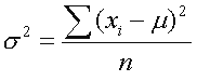
Determines the variance of all pixels in the selected area of a specific plane. The SVVariance property describes the variance in the selected area of a specific plane (only if the ProcessFlag property is TRUE for this plane). To get the variance of a specific plane simply switch to the plane with the PlaneIndex property before you use the SVVariance property.
The variance is calculated as follows:
.
| [out] | SVVariance | Variance of all pixels. |