Common Vision Blox provides two different types of Areas of Interest (AOIs):
Frames/Rectangles
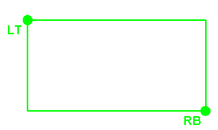
Frames are rectangles with horizontal and vertical edges.
Frames are used by CVB Tools or functions which are restricted to use areas with horizontal and vertical edges and no rotation.
For further information, you can look up for example the function CreateImageMap.
Refer Tutorial: %CVB%Tutorial\Image Manager\VB.NET\VBMapper.NET
One rectangular frame is defined by 2 points: the Left Top (LT) and the Right Bottom (RB) corner points along with their positions SrcLeft, SrcTop, SrcRight, SrcBottom.
The type declaration of frames is built analogically to the Windows RECT structure:
|
|
Type TDRect Left As Double Top As Double Right As Double Bottom As Double End Type |
 |
The frame coordinates can be extracted with the Display control method GetSelectedArea.
Please take in mind that this method returns the TArea Structure with 3 points.
Dragging frames with the mouse causes RectDrag or RectDraged events being created from the Display control.
See the sample code below.
Sample Code:
cvDispSrc.LeftButtonMode = LB_FRAME
Sub DoMap()
Dim ImgDst As Long<Dim x0#, y0#, x1#, y1#, x2#, y2# ' in VB necessary for areas
cvDispSrc.GetSelectedArea x0, y0, x1, y1, x2, y2 'get selected area
CreateImageMap cvImgSrc.Image, x0, y0, x2, y1, x2 - x0, y1 - y0, ImgDst 'create a image map based on the rect SrcLeft, SrcTop, SrcRight, SrcBottom
cvDispDst.Image = ImgDst ' display result image ReleaseObject ImgDst ' release tmp image
cvDispDst.Refresh ' refresh display
End Sub
Areas
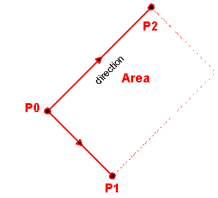
Areas are parallelograms with any desired angle.
Areas are used by a lot of CVB Tools or functions.
For examples, look up the function ImageHistogram.
Refer Tutorial: %CVB%Tutorial\Image Manager\VB.NET\VBRotateArea.NET
Parallelograms are defined by three vectors with respect to the origin of the coordinate system (CS Origin): P0, P1 and P2 with their positions X0, Y0, X1, Y1, X2 and Y2 respectively.
Therefore, adjacent edges do not have to be perpendicular to each other.
Such parallelograms cannot be drawn up with the mouse, only by programming.
The type declaration for areas is:
Type TArea X0 As Double Y0 As Double X1 As Double Y1 As Double X2 As Double Y2 As Double End Type |
 |
Areas can also be created by use of the SetSelectedArea method of the display control.
The area coordinates can be extracted with the GetSelectedArea method of the Display Control .
Areas can be dragged, rotated or changed interactively with the mouse.
This causes events of the types AreaDrag or AreaDraged being sent from the Display control.
To convert a rectangle with 2 corner points to a TArea structure with 3 points, use the function SetRectArea.
Bounding Rectangle
There are special cases where the user has to convert an Area in a TDRect structure.
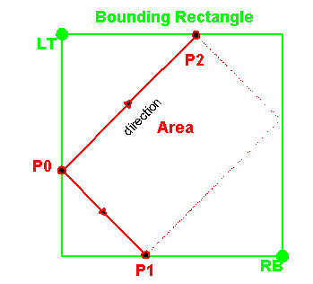
A common way to achieve this is to use the smallest rectangle which completely encloses the area.
This task has to be implemented in user functions.
In CVB, the CreateSubImage function is declared with an area as input parameter Area.
This function converts the Area internally to the bounding rectangle.

Related Topics
Image Control - Property Pages
Display Control - Property Pages
Area Functions
Coordinate System, Origin and Areas