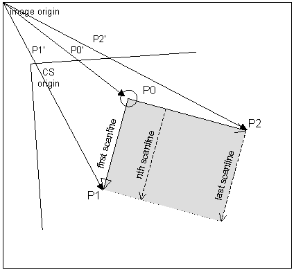
This section discusses two of the most powerful features of Common Vision Blox: the coordinate system and the selection of subareas of an image (defined by P0, P1, and P2).
Coordinate System
Normally the coordinate system of an image is fixed by the image itself.
The origin is at the top left corner. The x axis extends along the top of the image, and the y axis extends down the left side.
The unit of measure is one pixel. Points, rotations, subimages and the sizes of features in an image are all defined with respect to the image coordinate system.
The coordinate system is implicit in the image, it overlays the image and is established according to your instructions. You specify the origin, determine the orientation and define the unit of measure.
Thus, you control the structure on which positions, rotations and areas are based.
Dynamically within Common Vision Blox you can specify the virtual origin within an image to which all other points relate, it is also possible to do any or all of the following :
•Change the virtual size and orientation of an image
•Change the coordinate system at runtime based on the results of a found pattern
•Set the origin to be the position of a pattern or a position defined with respect to a pattern
•Rotate the coordinate system to the angle of a pattern or the angle of a line between the origin and a pattern
•Change its scale to the distance between a pattern's position and some predetermined reference point, or a fraction of that distance
When you specify an area of interest (AOI) in a SubImage, Histogram or other task which uses the area structure, the area is fixed with respect to the coordinate system in effect at the time the task executes.
This means that the AOI is translated, rotated or scaled according to changes made dynamically in the coordinate system.
Because of this capability and the fact that you can define the CS with respect to a defined position, you can :
•Define a search area or a subimage with respect to a given position
•Create loops in which an AOI is moved dynamically as the given position changes
Note: The rest of this section discusses these features in more detail.
Refer to chapter Areas for further information on defining subareas, their orientation and controlling the search direction within them.
In many applications a flexible coordinate system can be a helpful tool.
The coordinate system in Common Vision Blox consists of the origin and a matrix defining the linear transformation of the image.
A linear transformation can be described by a matrix A where:

The matrix A acts on any vector according to the equation:
A<x, y> = <x', y'> = <x*a11 + y*a12, x*a21 + y*a22>
Since each pixel in an image can be considered as a vector <x, y>, the matrix A acts on each pixel according to equation I, thus accomplishing linear transformation.
For example, the matrix A defined below acts on an image by doubling its height and doubling its width (a scaling factor of two).

So any pixel <x, y> in the image is transformed into the pixel <x', y'> where, by equation I:
<x', y'> = <x*2 + y*0, x*0 + y*2> = <2x, 2y>
Consider the pixel <50, 80>: A<50, 80> = <2*50, 2*80> The unit of measure becomes 1/2 pixel rather than 1, thus increasing the virtual size of the image to 200% of its actual size.
It is not essential for an application to support the coordinate system but it is often a very useful tool. This calculates the position of a point P (without CS) to a position in the image CS system:
P' = P * CS + Origin
Changing the origin and CS vector
The coordinate system provides a reference system for the description of areas.
Using CVB DLLs you can reset the origin and the CS vector dynamically.
When the first BMP image is loaded, the CS origin is at the top left corner (x = 0, y = 0).
The coordinate system vector (CS vector) that describes the scale and rotation of the coordinate system is <1, 0, 0, 1> (given in pixel coordinates).
Its equivalent polar form is polar (1,0) in which the modulus (first coordinate) indicates that the image is at a 1:1 scale, and the argument (second coordinate) indicates that the coordinate system is rotated an angle of 0° from the top border of the image.
The flexibility of the CVB coordinate system allows you to move an image into the »right« place (translation), give it the »right« orientation (rotation), and change it to the »right« size (scaling) while you are looking at it.
The CS origin defines the translation by specifying the pixel coordinates of the coordinate systems origin, relative to the top left corner of the image (y-axis increases downward).
The CS vector describes the combined effects of rotation and scaling. Its modulus is the scaling factor and its argument is the angle of rotation.

The vectors are defined as follows:
P0 The origin point of the parallelogram. The task is performed in relation to it
P1 The corner that defines the direction of scan lines in the parallelogram
P2 The corner that defines the search direction in the parallelogram
P0', P1', and P2' are the standard vector variables CurrentP0, CurrentP1, and CurrentP2, and are calculated according to the following equation:
Pn' = Pn * CS + Origin
where CS is the current CS vector and Origin is the current CS origin.

P0, P1, and P2 are defined in relation to the current CS and remain fixed with respect to it.
So, as the CS is translated, rotated, or sized so is the subarea. P0', P1', and P2' are defined in relation to the current image, therefore they change according to changes in the CS.
Setting the subimage orientation and direction
Through definitions of P0, P1, and P2, you control the orientation of the subimage as well as its size, shape and location.
So for example you can 'Cut Out' a subimage whose sides are not parallel to the sides of the image.
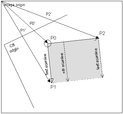
When the subimage becomes the current image, P0 is the origin, P1 defines the x axis, and P2 defines the y axis.

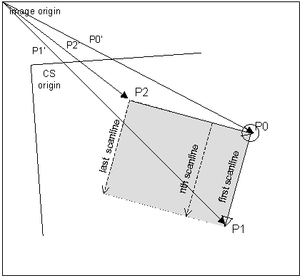
If you want to keep a subarea you have selected, but want it rotated (by 90°, for example) when it is passed into the data frame, simply change the settings of P0, P1, and P2 so that they specify different corners of the same rectangle. (Compare this illustration to the previous one.)
In Scan tasks (ScanPlaneUnary, ScanPlaneBinary, ScanImageUnary and ScanImageBinary), these vectors also determine the scan direction and search direction.
So, by controlling the vectors you can change the scan direction.
The first scan line is always from P0 to P1, and the scan direction is always from P0 to P2.
Related Topics
Image Control - Property Pages
Image Dll - Coordinate System Functions