The Common Vision Display Control is used to display images in a simple and user-friendly way.
When the Common Vision Display Control has been included in a project you may add a display window to your own application by means of the following icon.
![]()
The Display control supports:
Selection of the color channel view
Using the RedPage, GreenPage and BluePage properties you can determine which image plane is to be shown as the red, green or blue page.
In this way all the images of a color sequence can be shown in color or each color channel displayed individually as a gray scale image.
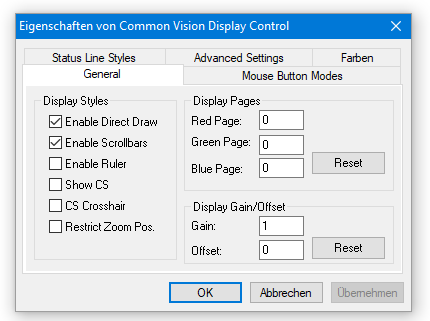
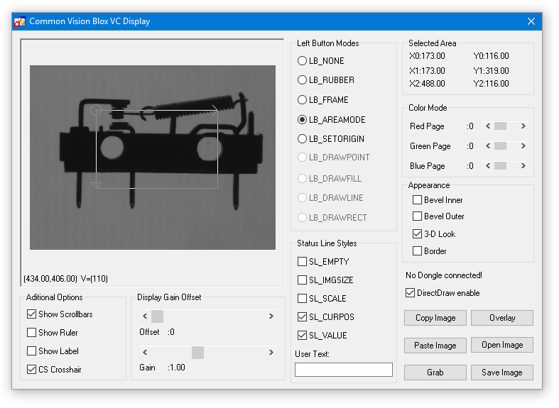
The GENERAL tab contains the general options for the Display settings.
Tab Status Line Styles
Displaying information in the status bar
In the status bar you can display the gray scale value of the pixel (SL_VALUE) under the cursor position, the location of the cursor (SL_CURPOS), the image size (SL_IMGSIZE), the actual zoom factor (SL_SCALE) and also a user-defined text string .
You can control the required condition of the status bar with the Statusline properties (SL_xxx).
If no status bar is to be shown, all the SL_xxx properties must be set to FALSE.
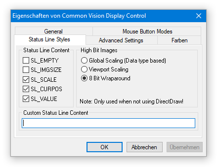
Enable the status bar display of interest by activating the SL_xxx control boxes.
Tab Mouse Button Modes
The following functions are controlled by the RightButtonMode property.
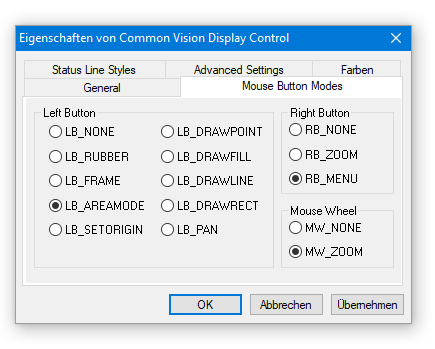
Options of the LeftButtonMode property to define the functionality of the left mouse button.
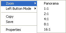
There are the possibilities to select RB_NONE , RB_ZOOM and RB_MENU. Here a screenshot of the RB_Menu selection.
Interactive zooming of images
There are three ways of zooming interactively :
Firstly, you can set the zoom factor on a contact menu (RB_MENU) which you open by pressing the right mouse button.
Secondly you can zoom directly with the aid of the right mouse button (RB_ZOOM) .
In order to magnify the view, hold down the right mouse button in the image section of interest.
Release the mouse button when the cursor has become a magnifier.
To reduce the view move the cursor to the desired location and press the right mouse button briefly.
You can control the function of the right mouse button with the RightButton-Mode property.
If the entire image is larger than the display area, use the ShowScrollbars property to get scroll bars which allow you to move to and display all regions of an image.
The third way to zoom the image is to use the mouse wheel. By doing this the zoom factor is increased or decreased, depending on the direction of the wheel.
The maximum zoom factor in this mode is higher (64.0) than in the other to modes which supports 16 as the maximum zoom factor.
The mode also allows you to zoom the image by values lower than 1.0 and by values other than PANORAMA, 1, 2, 4, 8 or 16. By holding down the 'CTRL' key on the keyboard while using the mouse wheel smaller steps are used.
The following functions are controlled by the LeftButtonMode property.
Drawing rectangles or areas (AOIs)
For the subsequent processing steps you first need to define an area of interest (AOI) in the image.
In Common Vision Blox you can define two types of AOIs: a »common« right-angled rectangle and an oblique aligned rectangle, i. e. the coordinate system of the AOI is oriented in an angle.
This allows you to process diagonal image areas.
The oblique aligned rectangle is described by three points - P0, P1 and P2.
Information on the AOI is displayed in the status bar:
When you place the cursor on the border of the rectangle you will see in the status bar the left, top, right and bottom position coordinates (LTRB = Left, Top, Right, Bottom) describing the AOI.
An oblique AOI is described through the coordinate origin (circle) and two arrow-heads.
When you place the cursor on one of these elements the status bar displays the coordinates of P0, P1 and P2.
More information see in chapter Areas of Interest.
Drawing an AOI
To draw an AOI place the mouse cursor at one of the AOI corners and press the left mouse button.
Hold this button down and move the mouse from this corner of the rectangle to the opposite one.
If you now release the button you exit the drawing mode.
A rectangle is shown on the monitor which marks the edges of the selected AOI.
LB_FRAME selects a right-angled AOI and LB_AREAMODE selects an oblique AOI.
Moving an AOI
To move a rectangle, place the mouse cursor approximately in the center of the AOI.
In an oblique AOI locate the cursor on the coordinate origin.
As soon as the mouse cursor becomes a cross with arrows in four directions press the left mouse button and move the AOI to the new location.
Modifying the size of an AOI
To vary the size of a right-angled AOI place the cursor on one of the edges.
In an oblique AOI place the cursor on one of the two arrow-heads.
The cursor changes and becomes a double arrow.
Now press the left mouse button and hold it down until you have drawn the AOI to the desired size.
Rotating an AOI
You can change the angle of an oblique AOI.
Place the mouse cursor on one of the two arrow-heads.
The cursor changes and becomes a double arrow.
Now press the left mouse button, hold it down and rotate the AOI.
When you have reached the angle you wanted exit this mode and release the mouse button.
Deleting an AOI
Click with the left mouse button in the image outside the AOI - the AOI will be removed.
Measuring distances and angles
You can interactively measure distances and angles if the LeftButtonMode property is enabled.
To do this, left-click the starting position and hold the button down.
Moving the mouse in this mode causes information to be displayed in the status bar.
The distance and angle (clockwise, starting at the positive x-axis) related to the starting point are measured and shown.
Altering the coordinate origin of the image interactively
In the property LeftButtonMode LB_SETORIGIN you can alter the coordinate origin of the image.
To do this, click on the desired position in the image.
If the ShowCS property is set the coordinate origin will be shown either as a crosshair (CoordStyle = CS_CROSSHAIR) or as an angle (CoordStyle = CS_NORMAL).
Drawing interactively in the overlay plane of the image
To change the overlay interactively the LeftButtonMode property can be set to the values LB_DRAWPOINT, LB_DRAWFILL, LB_DRAWLINE or LB_DRAW-RECT.
Depending on the chosen parameters you can draw either a point, fill in a closed area, draw a line or a rectangle.
The image must be converted into an overlay-capable image beforehand by means of MakeOverlayImage.
Example Tutorial for this is VCSizableDisplay in %CVB%Tutorial\ImageManager\VC directory.
Use right mouse key => Properties over an opened image.
CVB Tutorial showing the Display Control Properties
The CVB Image Manager Tutorials VB Display (VBDemo.NET) and VC Display (VC Demo) show the use of the Display Control.
Refer %CVB%Tutorial\ImageManager directory.
Numerous settings for the image display and handling are made in the Common Vision Display Control .