Functions | |
| cvbres_t | ApplyColorTwistMatrix (IMG ImgIn, double A11, double A12, double A13, double A14, double A21, double A22, double A23, double A24, double A31, double A32, double A33, double A34, IMG &ImgOut) |
| Converts an RBG image into an image with an user-defined color model using a color twist matrix. More... | |
| cvbres_t | ApplyForwardGammaCorrection (IMG ImgIn, IMG &ImgOut) |
| This function performs gamma-correction on the source image. More... | |
| cvbres_t | ApplyInverseGammaCorrection (IMG ImgIn, IMG &ImgOut) |
| This function performs the inverse gamma-correction on the source image. More... | |
| cvbres_t | ConvertHLSToRGB (IMG ImgIn, IMG &ImgOut) |
| Converts an HLS (hue, lightness, saturation) image to the RGB color model. More... | |
| cvbres_t | ConvertHSVToRGB (IMG ImgIn, IMG &ImgOut) |
| Converts an HSV (hue, saturation, value) image to the RGB color model. More... | |
| cvbres_t | ConvertLabToRGB (IMG ImgIn, IMG &ImgOut) |
| Converts an CIE Lab image to the RGB color model. More... | |
| cvbres_t | ConvertLUVToRGB (IMG ImgIn, IMG &ImgOut) |
| Converts an CIE LUV image to the RGB color model. More... | |
| cvbres_t | ConvertRGBToGrayScale (IMG ImgIn, double CoeffRed, double CoeffGreen, double CoeffBlue, IMG &ImgOut) |
| Converts an RGB image into a gray scale image using user-definable weights for the tree planes of the RGB input image. More... | |
| cvbres_t | ConvertRGBToGrayScaleStandard (IMG ImgIn, IMG &ImgOut) |
| Converts an RGB image into a gray scale image using standard weights for the conversion. More... | |
| cvbres_t | ConvertRGBToHLS (IMG ImgIn, IMG &ImgOut) |
| Converts an RGB image to the HLS (hue, lightness, saturation) color model. More... | |
| cvbres_t | ConvertRGBToHSV (IMG ImgIn, IMG &ImgOut) |
| Converts an RGB image to the HSV (hue, saturation, value) color model. More... | |
| cvbres_t | ConvertRGBToLab (IMG ImgIn, cvbbool_t UseLab16, IMG &ImgOut) |
| Converts an RGB image to the CIE Lab color model. More... | |
| cvbres_t | ConvertRGBToLUV (IMG ImgIn, IMG &ImgOut) |
| Converts an RGB image to the CIE LUV color model. More... | |
| cvbres_t | ConvertRGBToXYZ (IMG ImgIn, IMG &ImgOut) |
| Converts an RGB image to the CIE XYZ color model. More... | |
| cvbres_t | ConvertRGBToYCbCr (IMG ImgIn, IMG &ImgOut) |
| Converts an RGB image to the YCbCr color model. More... | |
| cvbres_t | ConvertRGBToYCC (IMG ImgIn, IMG &ImgOut) |
| Converts an RGB image to the YCC color model. More... | |
| cvbres_t | ConvertRGBToYUV (IMG ImgIn, IMG &ImgOut) |
| Converts an RGB image to the YUV color model. More... | |
| cvbres_t | ConvertXYZToRGB (IMG ImgIn, IMG &ImgOut) |
| Converts an CIE XYZ image to the RGB color model. More... | |
| cvbres_t | ConvertYCbCrToRGB (IMG ImgIn, IMG &ImgOut) |
| Converts an YCbCr image to the RGB color model. More... | |
| cvbres_t | ConvertYCCToRGB (IMG ImgIn, IMG &ImgOut) |
| Converts an YCC image to the RGB color model. More... | |
| cvbres_t | ConvertYUVToRGB (IMG ImgIn, IMG &ImgOut) |
| Converts an YUV image to the RGB color model. More... | |
| cvbres_t ApplyColorTwistMatrix | ( | IMG | ImgIn, |
| double | A11, | ||
| double | A12, | ||
| double | A13, | ||
| double | A14, | ||
| double | A21, | ||
| double | A22, | ||
| double | A23, | ||
| double | A24, | ||
| double | A31, | ||
| double | A32, | ||
| double | A33, | ||
| double | A34, | ||
| IMG & | ImgOut | ||
| ) |
Converts an RBG image into an image with an user-defined color model using a color twist matrix.
The color twist matrix is defined as following formula: <img class="ToDisplay" src="ColorTwist.gif" align="left" alt="Color Twist"><p> </p><p> </p> <p> </p>

In fact many color space conversions carried out by specialized functions in the CVFoundation.dll may be expressed as a set of coefficients A11 to A34 in the above equation. For example, applied by the function ConvertRGBToYUV, the following set of coefficients yields a transformation into the YUV color space: 

Another potential use is to independently apply scale and offset values for the R, G and B channel to adjust the color balance of an image: 

| [in] | ImgIn | Handle of image object. |
| [in] | A11 | Color twist matrix coefficients as indicated above. |
| [in] | A12 | Color twist matrix coefficients as indicated above. |
| [in] | A13 | Color twist matrix coefficients as indicated above. |
| [in] | A14 | Color twist matrix coefficients as indicated above. |
| [in] | A21 | Color twist matrix coefficients as indicated above. |
| [in] | A22 | Color twist matrix coefficients as indicated above. |
| [in] | A23 | Color twist matrix coefficients as indicated above. |
| [in] | A24 | Color twist matrix coefficients as indicated above. |
| [in] | A31 | Color twist matrix coefficients as indicated above. |
| [in] | A32 | Color twist matrix coefficients as indicated above. |
| [in] | A33 | Color twist matrix coefficients as indicated above. |
| [in] | A34 | Color twist matrix coefficients as indicated above. |
| [out] | ImgOut | Image handle of result image. |
This function performs gamma-correction on the source image.
The gamma correction converts an RGB image to the
gamma-corrected R'G'B' image based on following equations: \n
For R,G,B < 0.018:
<table border="0"><tr><td>R'</td><td> = </td> <td> 4.5 * R </td></tr>
<tr><td>G'</td><td> = </td> <td> 4.5 * G</td></tr>
<tr><td>B'</td><td> = </td> <td> 4.5 * B </td></tr></table>
For R,G,B >= 0.018:
<table border="0"><tr><td>R'</td><td> = </td> <td> 1.099 * R<sup>0.45</sup> - 0.099 </td></tr>
<tr><td>G'</td><td> = </td> <td> 1.099 * G<sup>0.45</sup> - 0.099</td></tr>
<tr><td>B'</td><td> = </td> <td>1.099 *  B<sup>0.45</sup> - 0.099</td></tr></table>
Please note that the channel intensity values are normalised to fit in the range of [0..1].
The gamma value is equal to 1/0.45 = 2.22 in conformity with ITU-R Recommendation BT.709.
After gamma correction the value range is reset to its original one.
| [in] | ImgIn | Handle to image object. |
| [out] | ImgOut | Image handle to result image. |
This function performs the inverse gamma-correction on the source image.
The inverse gamma correction converts the
gamma-corrected R'G'B' image back to the original RGB image to  based on following
equations: \n
For R',G',B' < 0.0812:
<table border="0"><tr><td>R</td><td> = </td> <td> R'/4.5 </td></tr>
<tr><td>G'</td><td> = </td> <td> G'/4.5</td></tr>
<tr><td>B'</td><td> = </td> <td> B'/4.5 </td></tr></table>
For R',G',B' >= 0.0812:
<table border="0"><tr><td>R</td><td> = </td> <td> ((R' + 0.099)/1.099)<sup>22</sup> </td></tr>
<tr><td>G</td><td> = </td> <td> ((G' + 0.099)/1.099)<sup>22</sup></td></tr>
<tr><td>B</td><td> = </td> <td> ((B' + 0.099)/1.099)<sup>22</sup></td></tr></table>
Please note that the channel intensity values are normalised to fit in the range of [0..1].
The gamma value is equal to 1/0.45 = 2.22 in conformity with ITU-R Recommendation BT.709.
After gamma correction the value range is reset to its original one.
| [in] | ImgIn | Handle of image object. |
| [out] | ImgOut | Image handle of result image. |
Converts an HLS (hue, lightness, saturation) image to the RGB color model.
This is the inverse function of \ref ConvertRGBToHLS.
| [in] | ImgIn | Handle of image object. |
| [out] | ImgOut | Image handle of result image. |
Converts an HSV (hue, saturation, value) image to the RGB color model.
This is the inverse function of \ref ConvertRGBToHSV.
| [in] | ImgIn | Handle of image object. |
| [out] | ImgOut | Image handle of result image. |
Converts an CIE Lab image to the RGB color model.
This is the inverse function of \ref ConvertRGBToLab.
16 bit Lab images as created by \ref ConvertRGBToLab are automatically treated correctly.
| [in] | ImgIn | Handle of image object. |
| [out] | ImgOut | Image handle of result image. |
Converts an CIE LUV image to the RGB color model.
This is the inverse function of ConvertRGBToLUV.
| [in] | ImgIn | Handle of image object. |
| [out] | ImgOut | Image handle of result image. |
| cvbres_t ConvertRGBToGrayScale | ( | IMG | ImgIn, |
| double | CoeffRed, | ||
| double | CoeffGreen, | ||
| double | CoeffBlue, | ||
| IMG & | ImgOut | ||
| ) |
Converts an RGB image into a gray scale image using user-definable weights for the tree planes of the RGB input image.
The output pixel values are calculated as \n
I = CoeffRed * R + CoeffGreen * G + CoeffBlue * B  \n\n
This function is similar to the Image Manager function CreateColorTransform, but accepts only 3-planar input images.
| [in] | ImgIn | Handle of image object. |
| [in] | CoeffRed | Weight for the red plane. |
| [in] | CoeffGreen | Weight for the green plane. |
| [in] | CoeffBlue | Weight for the blue plane. |
| [out] | ImgOut | Image handle of result image. |
Converts an RGB image into a gray scale image using standard weights for the conversion.
It is in principle identical with the \ref ConvertRGBToGrayScale function, but using fixed weights: \n
I = 0.299 * R + 0.587 * G + 0.114 * B  \n\n
These fixed weights mimic the human perception of different colors, thus producing a more natural gray-scale representation of your color
image than e.g. a uniform weighting of the red, green and blue components.
| [in] | ImgIn | Handle of image object. |
| [out] | ImgOut | Image handle of result image. |
Converts an RGB image to the HLS (hue, lightness, saturation) color model.
The HLS color model is very similar to the HSV color model. It consists of three components: Hue, Saturation and Lightness. \n
<ul>
<li> \b Hue defines the color of a pixel and is usually in the range of 0 to 360 (in this implementation downscaled to a range of 0 to 255),
beginning and ending with red and running through green, blue and all the intermediate colors. </li>
<li> \b Saturation indicates the degree to which the hue differs from a neutral gray. Usually values range from 0 (gray) to 1 (pure color).
In this implementation the range has been stretched to 0...255. </li>
<li> \b Lightness gives the intensity value, ranging from 0 (black) to 1 (white) - again stretched to 0...255. </li>
</ul>
The difference between HLS and HSV is the saturation maximum. While in the HSV color model, the maximum saturation (S = 1)
is reached at full Illumination (V = 1), in HLS the saturation maximum is reached for L = 0.5.
The most common graphical representation of the HLS color space is a double cone in a cylindrical coordinate system,
where H is used as the angular coordinate, L is the vertical axis and S is the distance from the vertical axis:
<img class="ToDisplay" src="HLSCone.png" align="left" alt="HLS Cone"><p> </p><p> </p> <p> </p><p> </p><p> </p><p> </p>
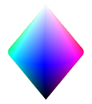
This is an example of a cut through the HLS cone at L = 0.5, represented as a square where H cycles from 0 to 360 along the vertical axis and S runs from 0 to 1 along the horizontal axis: 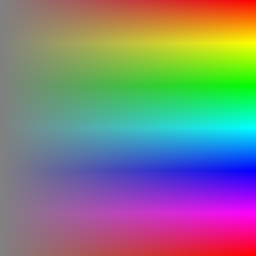

| [in] | ImgIn | Handle of image object. |
| [out] | ImgOut | Image handle of result image. |
Converts an RGB image to the HSV (hue, saturation, value) color model.
The HSV color model is very similar to the HLS color model. It consists of three components: Hue, Saturation and Value.
<ul>
<li> \b Hue defines the color of a pixel and is usually in the range of 0 to 360 (in this implementation downscaled to a range of 0 to 255),
beginning and ending with red and running through green, blue and all the intermediate colors. </li>
<li> \b Saturation indicates the degree to which the hue differs from a neutral gray. Usually values range from 0 (gray) to 1 (pure color).
In this implementation the range has been stretched to 0...255. </li>
<li> \b Value gives the intensity value, ranging from 0 (black) to 1 (white) - again stretched to 0...255. </li>
</ul>
The difference between HLS and HSV is the saturation maximum. While in HSV color model, the maximum saturation (S = 1)
is reached at full Illumination (V = 1), in HLS the saturation maximum is reached for L = 0.5.
The most common graphical representation of the HSV color space is a cone in a cylindrical coordinate system,
where H is used as the angular coordinate, Vis the vertical axis and S is the distance from the vertical axis:
<img class="ToDisplay" src="HSVCone.png" align="left" alt="HSV Cone"><p> </p><p> </p> <p> </p>
<p> </p><p> </p> <p> </p><p> </p><p> </p> <p> </p>

Below are two examples of a cut through the HSV cone at V = 0.5 and V = 1.0, represented as a square where H cycles from 0 to 360 along the vertical axis and S runs from 0 to 1 along the horizontal axis:
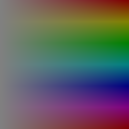 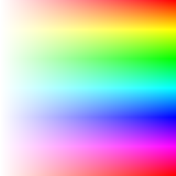
|  
|
| 0.5 | 1.0 |
| [in] | ImgIn | Handle of image object. |
| [out] | ImgOut | Image handle of result image. |
Converts an RGB image to the CIE Lab color model.
The CIE Lab format is derived from the CIE XYZ format (see \ref ConvertRGBToXYZ for details) and is considered to be perceptually uniform,
which means that colors that have the same distance in Lab space have the same perceptual distance,
which is achieved using a uniform chromaticity scale. The L parameter of a Lab color represents the uniform lightness of that color
(with values ranging from 0 to 100), while a and b are the red/blue and yellow/blue chromaticity values ranging from -128 to 127. \n\n
Conversion into Lab space is a two-step-process:
<ul>
<li> First the RGB input image is converted into CIE XYZ color space. </li>
<li> Then the transformation from CIE XYZ into CIE Lab is carried out according to the following formula:
<img class="ToDisplay" src="LabFormula.gif" align="left" alt="Lab Formula"><p> </p><p> </p> <p> </p><p> </p>
<p> </p><p> </p> <p> </p><p> </p><p> </p> <p> </p><p> </p><p> </p> <p> </p>
in which X<sub>n</sub> = 0.950455, Y<sub>n</sub> = 1.0 and Z<sub>n</sub> = 1.088753 are the coordinates of the D65 white point.
</li> </ul>
After this conversion, the dynamic range of the Lab values are spread to the dynamic range of the output image
(which is either 255 or 65535 for each component), depending on whether the output should be an 8 or 16 bits per pixel image. \n\n
Below are two samples of ab-planes for constant L values of 50 and 100 (a is increasing vertically
from -128 to 127, b is increasing horizontally from -128 to 127):
<table border="0">
<tr> <td> <img class="ToDisplay" src="128ab.png" align="left" alt="L=50"> </td>
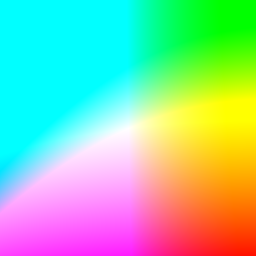


L = 50
L = 100
| [in] | ImgIn | Handle of image object. |
| [in] | UseLab16 | TRUE indicates a conversion to 16 bit Lab. FALSE means a conversion to 8 bit Lab. |
| [out] | ImgOut | Image handle of result image. |
Converts an RGB image to the CIE LUV color model.
The CIE LUV format is derived from the CIE XYZ format (see \ref ConvertRGBToXYZ for details) and is considered to be perceptually uniform,
which means that colors that have the same distance in Lab space have the same perceptual distance,
which is achieved using a uniform chromaticity scale. The L parameter of a LUV color represents the uniform lightness of that color
(with values ranging from 0 to 100), while U and V are the chromaticity values ranging from -134 to 220 (U) and -140 to 122 (V). \n\n
Conversion into LUV space is a two-step-process:
<ul>
<li> First the RGB input image is converted into CIE XYZ color space. </li>
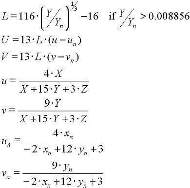
<li> Then the transformation from CIE XYZ into CIE LUV is carried out according to the following formula:
<img class="ToDisplay" src="LUVFormula.gif" align="left" alt="Lab Formula"><p> </p><p> </p> <p> </p><p> </p>
<p> </p><p> </p> <p> </p><p> </p><p> </p> <p> </p><p> </p><p> </p> <p> </p>
in which X<sub>n</sub> = 0.312713, Y<sub>n</sub> = 0.329016 (CIE chromaticity coordinates of the D65 white point) and
Y<sub>n</sub> = 1.0 (luminance of the D65 white point)
</li> </ul>
After this conversion, the dynamic range of the LUV values are spread to the dynamic range of the output image.\n\n
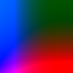
Below are two samples of UV-planes for constant L values of 50 and 100 (U is increasing vertically from -134 to 220,
V is increasing horizontally from -140 to 122):
<table border="0">
<tr> <td> <img class="ToDisplay" src="128UV.png" align="left" alt="L=50"> </td>
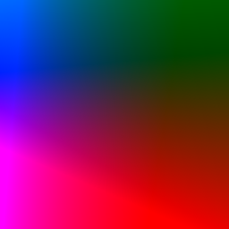
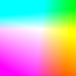

L = 50
L = 100
| [in] | ImgIn | Handle of image object. |
| [out] | ImgOut | Image handle of result image. |
Converts an RGB image to the CIE XYZ color model.
The CIE XYZ format is one of the oldest color space definitions, dating back to 1931. It is based on three hypothetical primaries, X, Y and Z that allow the description of all visible colors through a linear combination of positive X, Y and Z components. X, Y and Z are hypothetical primaries, because they do not actually map to any color that may be described as a wavelength. Y has been chosen such that it is very similar to a luminance component, while U and V contain most of the color information. \n\n The transformation of an RGB image is a simple matrix transformation of the RGB values using the following equation (note that this equation only holds for RGB values that have been normalized to the range [0..1]. Result values beyond the range [0..1] are usually saturated to that range): <img class="ToDisplay" src="FormulaXYZ.gif" align="left" alt="XYZ Formula"><p> </p><p> </p> <p> </p><p> </p><p> </p> After this conversion, the result values of X, Y and Z are then scaled to the dynamic range of the output image and then written into the output image. \n\n Below are three sample images of XZ planes for different values of Y: <table border="0"> <tr> <td> <img class="ToDisplay" src="X0Z.png" align="left" alt="Y = 0.0"> </td>
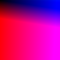

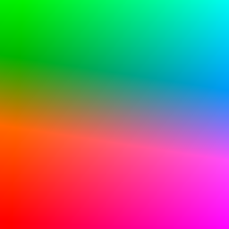

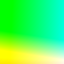

Y = 0.0
Y = 0.5
Y = 1.0
| [in] | ImgIn | Handle of image object. |
| [out] | ImgOut | Image handle of result image. |
Converts an RGB image to the YCbCr color model.
The YCbCr format is a slightly scaled and offset version of the YUV color space (see \ref ConvertRGBToYUV). The transformation may be described as a color twist matrix: <img class="ToDisplay" src="FormulaYCbCr.gif" align="left" alt="YCbCr Formula"><p> </p><p> </p> <p> </p><p> </p><p> </p> This equation is valid for input RGB values in the range [0...255]. Output values are saturated at the limits of the output data-type. \n\n Below are three sample CbCr planes for fixed values of Y: <table border="0"> <tr> <td> <img class="ToDisplay" src="0CbCr.png" align="left" alt="Y = 0"> </td>

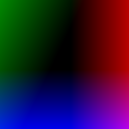
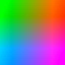

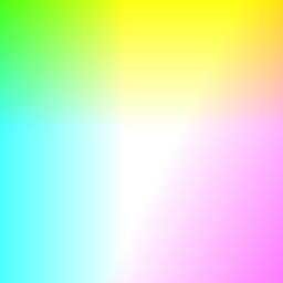

Y = 0
Y = 128
Y = 255
| [in] | ImgIn | Handle of image object. |
| [out] | ImgOut | Image handle of result image. |
Converts an RGB image to the YCC color model.
The YCC format was developed for encoding Photo CD image data and is based on using a luminance-chrominance color representation similar to that of YCbCr. The conversion formula for RGB values in the range [0...1] is <img class="ToDisplay" src="FormulaYCC.gif" align="left" alt="YCC Formula"><p> </p><p> </p> <p> </p><p> </p><p> </p> The result values in the range [0...1] are then spread to the dynamic range of the output image. \n\n These are three sample CC planes for fixed values of Y: <table border="0"> <tr> <td> <img class="ToDisplay" src="0CC.png" align="left" alt="Y = 0.0"> </td>

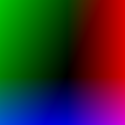
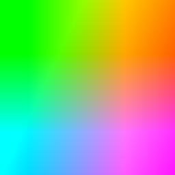

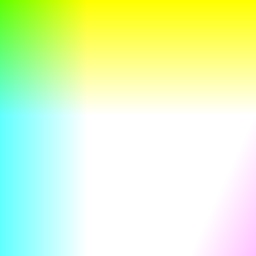

Y = 0.0
Y = 0.5
Y = 1.0
| [in] | ImgIn | Handle of image object. |
| [out] | ImgOut | Image handle of result image. |
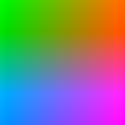
Converts an RGB image to the YUV color model.
The YUV color model is the basic color model for analog color TV broadcasting. It is made up of the luminance component (Y), computed as a weighted sum of red, green and blue, and the two color difference components (U, V), computed by subtracting luminance from blue and luminance from red. The advantage of this approach is the decoupling of the luminance component from the color components, allowing you to manipulate the luminance information without changing the color of the pixel. \n\n Conversion from RGB to YUV is done according to the formula <img class="ToDisplay" src="FormulaYUV.gif" align="left" alt="YUV Formula"><p> </p><p> </p> <p> </p><p> </p><p> </p> These are three sample UV planes for fixed values of Y: <table border="0"> <tr> <td> <img class="ToDisplay" src="0UV.png" align="left" alt="Y = 0"> </td>

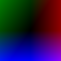

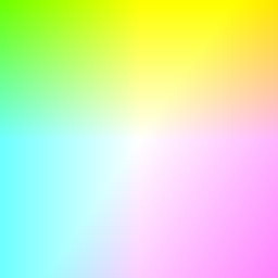

Y = 0
Y =128
Y = 255
| [in] | ImgIn | Handle of image object. |
| [out] | ImgOut | Image handle of result image. |
Converts an CIE XYZ image to the RGB color model.
This is the inverse function of \ref ConvertRGBToXYZ.
| [in] | ImgIn | Handle of image object. |
| [out] | ImgOut | Image handle of result image. |
Converts an YCbCr image to the RGB color model.
Following formula is used: <img class="ToDisplay" src="FormulaYCbCrToRGB.gif" align="left" alt="YCbCrToRGB Formula"><p> </p><p> </p>

| [in] | ImgIn | Handle of image object. |
| [out] | ImgOut | Image handle of result image. |
Converts an YCC image to the RGB color model.
Following formula is used: <img class="ToDisplay" src="FormulaYCCToRGB.gif" align="left" alt="YCCoRGB Formula"><p> </p><p> </p>

| [in] | ImgIn | Handle of image object. |
| [out] | ImgOut | Image handle of result image. |
Converts an YUV image to the RGB color model.
Following formula is used: <img class="ToDisplay" src="FormulaYUVToRGB.gif" align="left" alt="YUVoRGB Formula"><p> </p><p> </p>

| [in] | ImgIn | Handle of image object. |
| [out] | ImgOut | Image handle of result image. |