The Advanced Configuration front-end is designed for experienced users who need to manage many devices and advanced device settings.
It can be opened
•using the Advanced Config button  of the GenICam Device Configurator or
• by launching the application %CVB%\Hardware\StemmerImaging\Utilities\GEVConfigManager.exe.
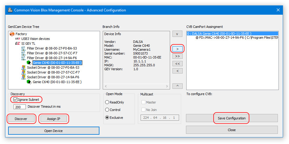
Initially, the Advanced Configuration looks like this:
Main Windows
GenICam Device Tree
The GenICam Device Tree shown in the left panel shows all GenICam devices currently detected by the system in a hierarchic tree that groups the devices by the driver through which they are being accessed and the device type. Generally speaking, the GenICam Device Tree is not limited to GigE vision devices, but throughout the rest of this section we assume that the device(s) you are working with is/are GigE vision cameras.
When your device has a connection and an assigned IP address you will see it listed in the GenICam Device Tree. The current status of the detected devices is indicated by different colors as follows:
 |
Device is reachable and not in use |
 |
Device is in use or not reachable |
 |
Device is read only (another application is controlling the camera with Open Mode "Control") |
 |
Device is reachable but on the wrong sub net |
 |
Device is not a GigE Vision device |
Discovery - Ignore Subnet
When your device is not listed in the Device Tree but connected to the network, it might have the wrong IP configuration.
To verify (and potentially fix) this, mark the "Ignore Subnet" check box to show all devices on the network (ignoring the host's current IP configuration) and press the "Discover" button.
When you have found your device, you can force an IP address and subnet mask on it using the "Assign IP" Button.
Assign IP
Since GigE Vision compliant cameras are generic networking devices, they have to be addressed with a unique IP address.
Addresses can be assigned both dynamically and statically.
By default, GigE vision cameras try to establish a connection to the host machine based on dynamically assigned addresses.
When plugged in, the camera first sends out a number of DHCP requests.
If no answer is received within a fixed period of time (usually 60 s), the systems tries to auto configure the network via the LLA (Link Local Address) addressing scheme.
LLA only works when both links are configured to use dynamically assigned IP addresses.
Static addressing, on the other hand, is available in two different forms.
Arbitrary addresses can be either:
•assigned persistently (Static IP)
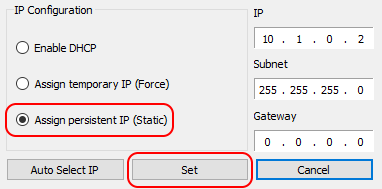
•assigned only until the next power cycle of the camera device (Force IP):
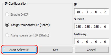
For testing purposes, dynamic addresses are more convenient, therefore while configuring the functionality of the camera system, this is usually the preferred mode.
The problem however is that dynamically assigned addresses are essentially random, which means that when more than one camera is available on a single network interface, a specific order cannot be guaranteed after a restart.
In a setup where every camera has its specific role, such behavior is generally undesirable. It is therefore recommended to switch to static addressing before deployment.
Branch Info and CVB CamPort Assignment
The Branch Info panel shows the device identification information of the currently selected device.
You can assign the currently selected camera to one of the GenICam.vin's virtual device ports using the ">" Button.
">>" adds all currently reachable devices to the GenICam.vin configuration that is being displayed in the right panel "CVB CamPort Assignment".
Likewise the buttons "<" and "<<" remove one or all cameras from the current GenICam.vin configuration and the buttons "^" and "v" allow reordering of the list of currently assigned devices.
Note that the index numbers displayed in front of each configured camera are the port numbers through which the respective camera will be accessible in Common Vision Blox.
Once you have finished the Assignment, click on "Save Configuration" to save the current configuration to the GenICam.ini-file and "Close" to close the Advanced Configuration and go back to the Standard Device Configuration.
Advanced Device Settings
The advanced Device Settings can be opened by double clicking one of the configured devices in the CVB CamPort Assignment panel.
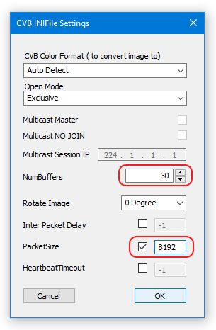
This will open a dialog in which several settings of the GenICam.ini file can be configured.
Note that many of these settings are also available through the device context menu in the GenICam Device Configurator.
CVB Color FormatSets the Color Format to either Raw, Mono 8 Bit, RGB 24, Mono 16 Bit or RGB 48. Raw means "no conversion" and is supposed to work with any camera any time as it simply passes on the raw output of the camera (identical to the Color Format setting in the Device Configurator).
CVB Device Open Mode•Exclusive: Device is being opened through a peer to peer connection for exclusive use by the host opening the device, blocking it for all other potential users. This is the default mode. •Control: For use when the opening host is the Multicast Master and is supposed to have control over the camera. •ReadOnly: For use when the opening host is a Multicast Slave i.e. it receives the camera's video stream, but has no control over the device.
Multicast MasterMulticast sessions allow multiple hosts to receive the data generated by a single camera. However, in such a scenario only one host can assume control of the camera. Check here if this host should assume the role of Multicast Master in a Multicast session.
Multicast Session IPThe IP address for the Multicast session. Note that your network switch must support this feature in order to use Multicast.
NumBuffersSpecify the number of buffers to be allocated when the driver is loaded. Generally speaking, a higher number of buffers can help make sure that no image is lost if CPU load peaks for a limited amount of time and image processing cannot keep up with image processing during that phase. However, an increased number of buffers of course also means increased memory consumption of the process (identical to the "Number of Buffers" settings in the Device Configurator).
Rotate ImageRotates the image by 0°, 90°, 180° or 270°. The image rotation is not applied to the image data, but by modifying the image's VPAT information, so the rotation comes at no additional cost. Note however that for some image processing algorithms the image rotation selected through this parameter may increase processing time (identical with the Rotate Image option in the Device Configurator).
Inter Packet DelaySpecifies the send delay between the camera's data packets. An increase in this delay reduces the peak bandwidth of a device but can help in situations where more than just one camera device is present on a network and the other device(s) experience bandwidth starvation while the camera is transmitting images.
Packet SizeSets the size of a data packet. Normally about 1500 byte, optimized with 8192. Higher values (also called jumbo packets or jumbo frames) may be used to reduce CPU usage. Note that the network interface must be configured to support jumbo frames too before setting higher values here!
Heartbeat TimeoutThe heartbeat is a small data package sent back and forth between the host and the camera to make sure the connection is still valid. If either side fails to respond for the amount of time specified here, the other side will assume that the connection is no longer needed. |
 |