|
|
Common Vision Blox 14.0
|
|
|
Common Vision Blox 14.0
|

Common Vision Blox Tool
 C-Style |  C++ | ") .Net API (C#, VB, F#) |  Python | |
| Match3D ICP: | Match3D.dll | Cvb::Match3D | Stemmer.Cvb.Match3D | cvb.match_3d |
| Match3D DNC: | CVDNCFind.dll | Cvb::Dnc | Stemmer.Cvb.Dnc | cvb.dnc |
This CVB tool consists of two libraries:
The Match3D DNC tool allows to locate objects described by a CAD file in point clouds. The Match3D ICP tool allows to align two point clouds. The alignment in this tool is based on the iterative closest point (ICP) algorithm.
| C-Style | C++ | .Net API (C#, VB, F#) | Python |
| Match3D.dll | Cvb::Match3D | Stemmer.Cvb.Match3D | cvb.match_3d |
In many production environments it is important that each product is checked for completeness and flaws. It is a common approach to compare a golden template image (model) with an image of the test object (part). Therefore the object's image is simply subtracted from the model image. However, in practice the two images have to be perfectly aligned. This requires a transformation prior to the comparison step in order to move the part to the same position and orientation of the model. For objects in 2D a translation in x and y and one rotation have to be found. Whereas, aligning objects in 3D (point clouds) is more complex. Here, a translation in x, y and z and a rotation about the x-, y-, and z-axis have to be estimated. This results in 6 Degrees of Freedom (DoF) for the 3D case, as opposed to 3 DoF in the 2D case.
The core part of the Match3D tool is following function which aligns two point clouds in all 6 DOF: CVM3DMatchDownsampledPointClouds
In addition, a function is provided calculating the RMS of two point clouds: CVM3DRmsDistanceOfPointClouds
Note, that general functions handling 3D data (e.g. computing the euler angels from a rotation matrix and vice versa, transforming point clouds, loading a point cloud from a file, etc...) are implemented in the Core3D.dll.
For the quality inspection of a part, it has to be compared to a model. Before the inspection part and model have to be perfectly aligned. The process of the alignment of two point clouds is described in the section Alignment. In order to compare the point clouds they have to be reprojected along the z-axis and their differences have to be computed (see section Comparision of two point clouds).
Before two surfaces can be compared to each other, they have to be properly aligned in 3D. This can be done using the function CVM3DMatchDownsampledPointClouds, the core part of Match3D. CVM3DMatchDownsampledPointClouds is based on the iterative closest point algorithm (ICP) that follows Arun K., Huang T., Blostein S. (1987) "Least-squares fitting of two 3-D point sets" in IEEE Trans Pattern Anal Machine Intell 9:698–700. It is based on a least-squares fit which iteratively estimates a translation in x, y, z and a rotation matrix with the angles about the x-, y- and z-axis (roll, pitch and yaw).
Although the ICP is a stable and fast algorithm a coarse pre-alignement of the point clouds is required. For a successfully matching both input surfaces must meet the following conditions:
The function CVM3DMatchDownsampledPointClouds needs as input two organized or unorganized point clouds saved as CVCOMPOSITE handle (see also the Core.dll). In addition several input parameters can be set:
With these parameters the accuracy of the alignment and the computation speed can be optimized. The output of CVM3DMatchDownsampledPointClouds is a translation vector (x, y, z) and a rotation matrix, stored in a CVC3DTransformation object.
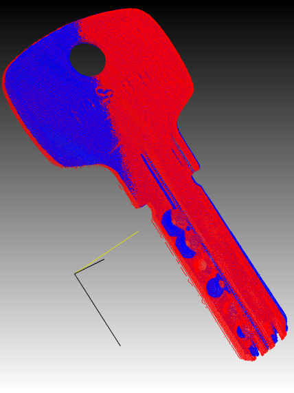
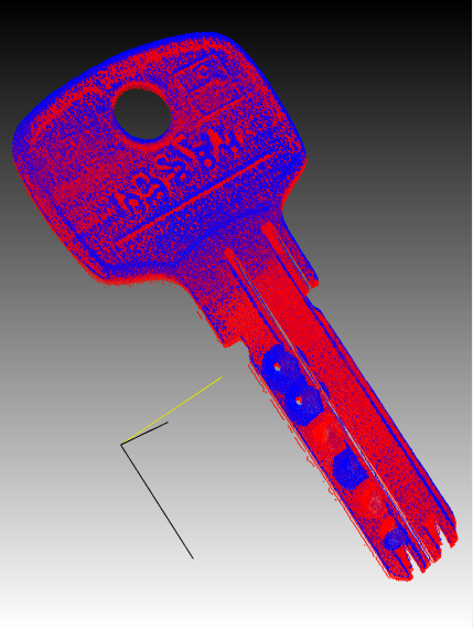
With the Core3D function CVC3DRollPitchYawFromRotationMatrix the euler angles (roll, pitch, yaw) can be computed from the rotation matrix (see Core3D.dll). In addition, a rough accuracy assessment of the matching results can also be done calculating the RMS with the function CVM3DRmsDistanceOfPointClouds. However, for the final quality inspection the differences between the model and the transformed point cloud have to be computed. This can be done by re-projecting the point clouds along the z-axis and computing the differences (see section Comparision of two point clouds). The following figures show two point clouds before (top) and after (bottom) the alignment. The blue points represent the model (golden template or reference object) and the red points represent the part to be inspected and aligned.
Since CVB 14.0 an improved alignement with function CVM3DMatchPointCloudsAdvanced is provided. The function matches two point clouds by an extended iterative closest point algorithm (ICP), which also takes shape correspondence into consideration. The point cloud may be pre-aligned using the center of gravity (if this option is selected by the user). Note, that the two objects may not be tilted by more than about 30° or even 60° depending on the their shape.
For the final quality inspection, the aligned point cloud has to be compared to the model. Therefore several functions of the Core3D.dll can be used: In a first step both point clouds (model and target) must be reprojected along the z-axis by the function CVC3DCreateRangeMapFromPointCloud. The output will be a 2D image, we call it a rectified range map. Afterwards, the point differences between both surfaces can be computed using the function CVC3DCreateDifferenceMap, which simply subtracts the previously generated rectified images from each other.
The whole process of matching and creating a disparity map is shown in the flow chart below.
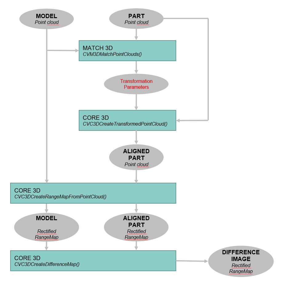
An example application can be found in %cvb%Tutorial\Match3D. A brief VC++ example is provided below.
Two point clouds are loaded and matched. Afterwards they are converted into rectified range maps and a difference map is created from these images.
| C-Style | C++ | .Net API (C#, VB, F#) | Python |
| CVDNCFind.dll | Cvb::Dnc | Stemmer.Cvb.Dnc | cvb.dnc |
DNC is a CAD-based 3D-object recognition tool.
It allows to locate objects described by a CAD file in point clouds. Only the geometric properties of the object are taken into account, its color and texture do not matter. This is where the name of the tool comes from: Depth No Color.
DNC is a two-stage detection tool.
Training itself is again divided into two steps.
For both of these steps - the generation of example poses from the CAD object, as well as the generation of a classifier from these example poses - some parameters have to be chosen with care.
In the detection step, the classifier operates on a point cloud and attempts to retrieve the previously trained object poses. In a sense, this also happens in two steps:
For both of these steps, some parameters must again be carefully adjusted.
The result of the object detection is a list of hits, each indicating the location and orientation of the object within the point cloud. If the sensor generating the point cloud is calibrated with a robot, the hit data can be transferred to the robot in order to grip the objects.
For the purpose of detecting objects DNC tests several templates for their appearance within the depth image of a 3D-sensor, using a similarity measure composed from oriented 2D- and 3D-features. These features are calculated both for the templates and the sensor's depth image. Whenever the similarity measure exceeds a certain threshold, a hypothesis is generated, indicating a possible hit at this location within the depth image. The hypotheses are verified by optimizing the 3D-pose at this location and obtaining several 3D-measurements, including a geometric similarity measure between object and point cloud, the degree of coverage, the degree of inconsistency and the degree of inconsistency which can be explained by occlusion. Only if all these measurements fall below or exceed a threshold value will the individual hypothesis be accepted and counted as a true hit.
The templates, also denoted "samples", are generated from a CAD file, which contains the object's geometric mesh data. To achieve this, an artificial sensor is pointed at the object and an artificial view of the object is calculated from its mesh data. Different views can be accomplished by either rotating the object in front of the sensor or changing the sensor position or both. The range of different views must cover the range of possible poses of the object which appear later on during detection. Obviously this can only be done in a discrete way, resulting in a finite number of templates.
The generation of templates - the viewport sampling - is done with a specified and constant spatial resolution. This resolution is then transferred to the classifier, which adapts the actual sensor resolution accordingly. For this reason the teaching process in DNC is independent of the 3D-sensor which is actually used later on. Of course, some considerations must be made in order to choose a reasonable value of this resolution.
To build an object detection system with DNC, you must have a CAD file of the object and you must know from which viewing direction the sensor will later perceive the object. In a first step, we convince ourselves that the CAD file is given in units of millimeters. Sometimes this is not the case.

Checking units of object's CAD file.
The resolution factor, which must be specified for template generation, is in pixels per millimeter and should be chosen as low as possible. There are some considerations about this resolution value:
It is also advantageous to add a fringe to the templates to ensure a proper extraction of the object's silhouette during the training process. During template generation you can convince yourself that relevant details are visible while template size is reasonably small.
|
Details of the object must be clearly visible... |
...while maintaining a reasonable small template size. |
The relative orientations between object and 3D-sensor are controlled by first choosing the appropriate sensor position and then changing object's orientations until all possible orientations are covered by the templates. In our example, we observe a conveyor belt from an angle above and want to detect the object independently of it's rotational position.

Objects in different rotations on a conveyor belt seen from above at an angle.
To generate appropriate templates for this scene, we simulate it accordingly. For the sensor's latitude we choose 35 degrees (0 degrees would generate a view from above, 90 degrees a view from the side) and let the object rotate around its own Z axis. In most cases, covering 360 degree rotation in 10 degree increments is sufficient, resulting in 36 templates.

Some of the 36 generated Templates.
If the objects will also appear in different poses on the conveyor belt, we must generate templates for this poses as well. For example, if we expect additional object poses like this
Additional poses, in which the object may appear...
we flip the object around its X axis about 90 degrees and generate additional 36 templates by again rotating the object around its Z axis

...and the corresponding additional templates.
and equally for an additional pose
A third possibility how the object could be situated...
we place the object accordingly (in this case flip around X axis about -90 degrees and set the Y Euler angle to 23 degrees:

...and the additional templates corresponding to this pose.
In this way we create as much templates as needed to cover the range of expected poses. If we have no information of the expected objects poses, we must cover the complete pose sphere around the object, including camera roll, resulting in thousands of templates. But usually the space of expected object poses is constrained and the number of templates is limited.
For classifier generation, the samples are analyzed and features are selected from each sample. The number of features is a scaling factor for the subsequent search time and should therefore be chosen as low as possible and as high as necessary.
Usually feature numbers in the range of 200 to 400 features per sample are sufficient to detect objects. In order to compensate for the discreteness of the generated samples, the features are locally distributed by some amount. This allows for object poses to be detected that lie between two generated views. In addition to the feature selection a sub-sampled voxel representation of each sample is generated, allowing for a fast pose optimization and thereby finally overcome the coarseness of the discrete sample generation. The sub-sampling factor also influences the subsequent detection time and should be chosen as high as possible.
The classifier is used to detect objects in a point cloud, which must be organized as a dense point cloud. As already pointed out, the samples serve as feature templates. Therefore, templates and point cloud must be oriented equally. We have stipulated two different point cloud orientations that can be used in a DNC recognition task. They differ in the way how the sensor's depth images are oriented. We call them "sensor frame orientation" and "object frame orientation".
In sensor frame orientation, the point cloud has its origin in the very center of the sensor. The Z-axis points towards the scene and the X-axis goes to the right (the horizontal direction of the sensor). Accordingly, Z-coordinates increase with increasing distance from the sensor.
|
A depth image of a 3D-sensor which delivers point clouds in sensor frame orientation. Depth values increase with increasing distances. |
3D-visualization of point cloud data. The sensor is positioned in the origin of the point cloud. |
In the object frame orientation the point cloud has its origin in a predefined distance from the sensor, while the Z-axis points in the direction of the sensor. Accordingly, Z coordinates increase with decreasing distance from the sensor. Again the X-axis points to right, thus resulting in reversed direction of Y.
|
A depth image of a 3D-sensor which delivers point clouds in object frame orientation. Depth values increase with decreasing distance to the sensor. |
3D-visualization of the point cloud. Its origin is situated at a predefined distance from the sensor. The Z-axis points towards the sensor. |
In both frame orientations DNC considers points with positive Z-coordinates only. Thus, in object frame orientation the origin of the coordinate system must be located behind the objects to be detected. Otherwise they are invisible to the classifier. DNC automatically detects which frame orientation is present.
During detection of objects the actual resolution of the dense point cloud is locally adjusted to the resolution with which the samples were generated. Each template that reaches a "Hypothesis-Threshold" is traded as a possible match and included in a list of hypotheses. This hypothesis threshold should be chosen as high as possible, usually values above 0.9 keep the hypotheses list reasonably short. Each hypothesis is then verified by first optimizing the pose match between template and point cloud (using the voxel representation of the sub-sampled template) and calculating geometrical measures. When theses measures match thresholds, which are specified in the search parameters, the hypothesis is added to the result list.
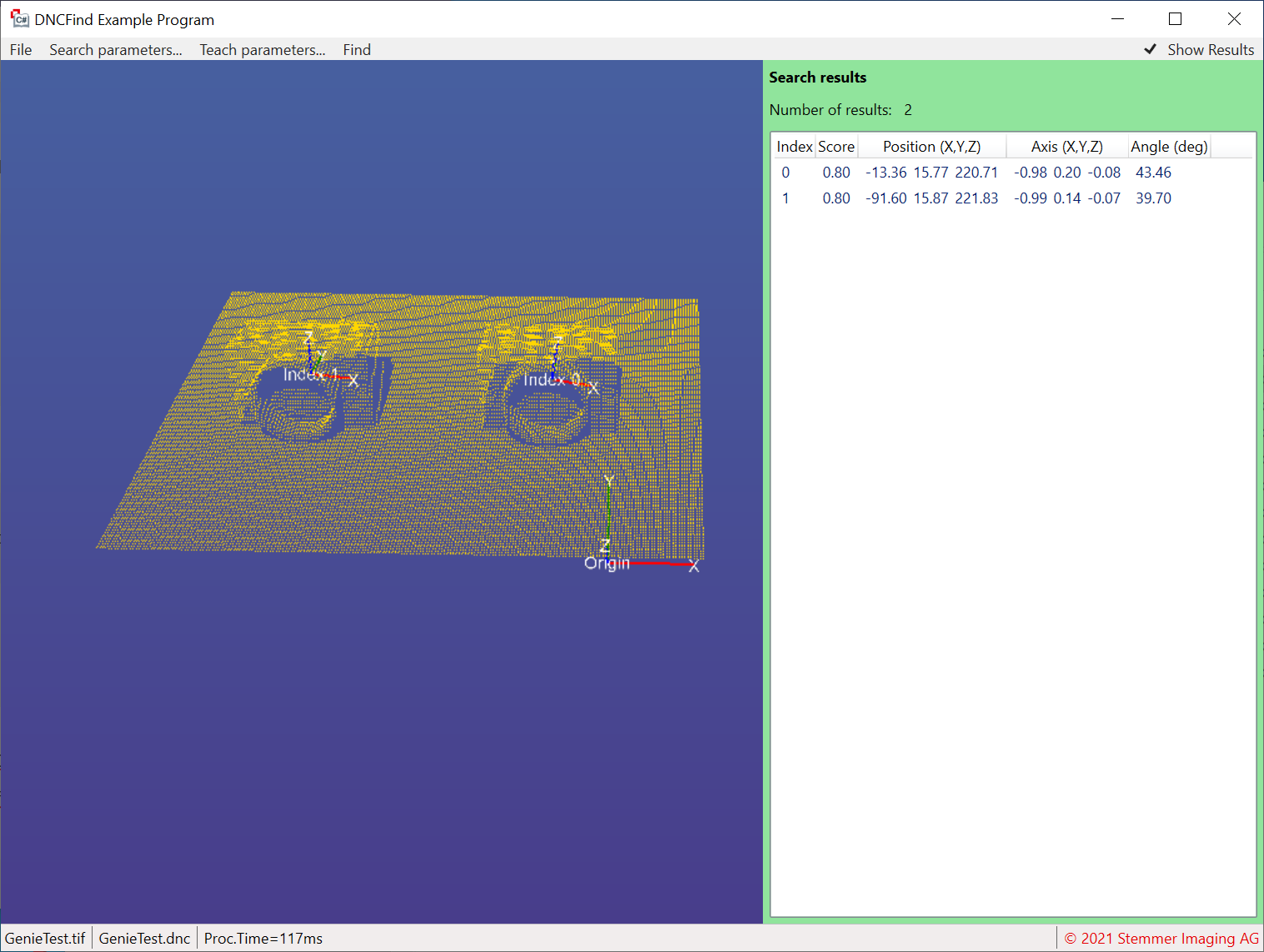
Each individual result in the result list contains information about the location and orientation of the object found, so the data can be used, for example, to guide a robot to the object.

A scene with objects to find. Sensor resolution is 640x480 pixels.
.")
The scene with the found objects overlaid (processing time about 500 ms).
.")
The same scene in much higher resolution of 1920x1080 pixels (processing time about 500 ms).
Note, that general functions handling 3D data (e.g. computing the euler angels from a rotation matrix and vice versa, transforming point clouds, loading a point cloud from a file, etc...) are implemented in the Core3D.dll.
Example applications can be found in %CVB%/Tutorials/DNC.