|
|
Common Vision Blox 14.0
|
|
|
Common Vision Blox 14.0
|

Common Vision Blox-Tool
 C-Style |  C++ | ") .Net API (C#, VB, F#) |  Python |
| CVCBlob.dll |
Image Processing Tool for Blob analysis
Blob is a Common Vision Blox tool for measuring various morphometric parameters in objects of any shape (contiguous pixel ranges) which are defined by means of a binary threshold (blobs and holes in blobs).
In this process, Blob does not analyze individual pixels but operates with a representation of contiguous object ranges in an image row – the run length code.
Each image row is coded in such a way that the start and end address in the X direction is stored for every contiguous object range.
This approach speeds up operations considerably compared with a pixel-based algorithm.
Then the adjacency of the object chords in the current row to the existing objects is analyzed, and the measurement parameters of these objects are updated accordingly.
Objects can be of any shape and complexity. They can also contain any number of holes, and these are also measured as objects. The object to which every hole belongs is known.
In order to adjust the measuring effort to different requirements, there are several extraction modes which define the parameters to be measured. In this way, Blob can be tailored to different requirements while still delivering optimum performance.
It is possible to make the return of measured values dependent on whether an object satisfies certain criteria (filters).
For instance, a pixel threshold can be set above which small objects that are frequently generated by noise are not recorded, or objects that touch an image border can be suppressed.
Further-more, Blob can generate the run length code of every object in the shape of a chained list which is also passed to the calling program.
This means the objects are available as a list of chords enclosing the object, and can thus be recovered if necessary. However, this requires more compute time and memory, and is not necessary for normal measuring operations in which properties such as size, center or perimeter are ascertained.
Features
Tool as well as Tutorials can be found under \cvb\Tutorial\Blob.
Abstract
With its extensive set of commands and options, CVB Blob may be considered a somewhat complicated tool.
But what at first sight seems unnecessarily complicated will turn out to be pure flexibility, once you have a grasp of the underlying concept.
This document is intended to help you get this grasp. We will show the general approach to working with Blob, but without listing every single function, Blob contains.
For a detailed description of all the functions and their parameters refer the API chapter.
General Overview
When working with CVB Blob Tool, operations can typically be split up in three different stages of operation:
Note: Those different steps refer only to CVB Blob Tool; you can of course have in your application several blocks containing those three stages, and you can of course terminate work on a blob object without terminating your application.
To work with Blob, first a blob object has to be created.
This blob object later takes up the results of the blob execution, and also contains a handle to the image object, on which blob is intended to work.
The blob object is created by calling the function BlobCreate. The return value (a void pointer) is a handle to a blob object, which is later passed to all other functions to be executed on the blob object in question.
Whether a blob handle is valid or not can be checked with the function BlobIsBlob, for Blob size determination BlobGetSize can be used.
Once the blob object is created, the parameters for later execution(s) should be set. Among those parameters are for example the maximum amount of memory, blob is allowed to occupy (BlobSetMaxMemory, BlobSetMaxNumBlobs), the maximum number of projections of the convex perimeter (BlobSetNumFeret).
Special emphasis should be given to the function BlobSetImage. You should keep in mind, that BlobCreate calls a ShareImage on the image that is provided.
Last but not least, any filter or sort modes (BlobGetLimit..., BlobSetLimit...,BlobSetSortMode...) for your results should also be set before execution!
The most important function is BlobExec. BlobExec executes the blob algorithm on the provided blob object.
If you want the execution results sorted, you should call BlobExec followed by BlobSort.
If the objects have been sorted by certain criteria (BlobSetSortMode), the index number corresponds to the entry in the sorted list.
This means that object 0 in an unsorted list is the first object found. If the object list has been sorted by size (area of the blob) in ascending order, blob 0 is the smallest blob.
If LastEntry was specified in the BlobSetSortMode function, this also applies to unsorted lists.
If LastEntry was set to 1, only one object is found (the first, last, biggest or smallest object for instance, depending on the mode).
Further execution methods are offered in Blob library.
BlobBinariseImage and BlobGetExecTime are more diagnostic functions.
Afterwards the results can be retrieved, using the Parameter Enquiry functions described in chapter Parameter Enquiry.
To properly terminate the blob tool it is necessary to release the memory occupied by the blob object. This is simply done by calling BlobDestroy on the blob object's handle.
This has (sooner or later) to be done for every single blob object that was created in stage 1 with BlobCreate (i. e. the number of calls to BlobCreate must match the number of BlobDestroy).
Because the execution time for BlobCreate and BlobDestroy take comparatively long to execute, it is recommendable to minimize their use.
This means, that you should not always destroy and re-create your blob object if you intend to run blob several times on the same image object (which does not necessarily mean the same image; if you grab several images from a framegrabber into one image object, the object handle itself is not changed and so there is no need for example to call BlobSetImage).
If, however, the image handle is changed, e. g. by a call to LoadImage or similar, you have to re-set the image using BlobSetImage.
All the above information leads to the following scheme, which, in very short form, depicts the general way CVB Blob should be used in any application:

Enquiries about object parameters are handled with various functions.
The first parameter for those functions always is the handle of the blob object, followed by an index indicating the blob whose parameters shall be extracted.
You can easily check how many blobs there are by calling BlobGetNumBlobs.
Then comes a list of the variables that are going to receive the blob's parameters.
Example program for getting the Blob Size and identify the centre of gravity of the object:
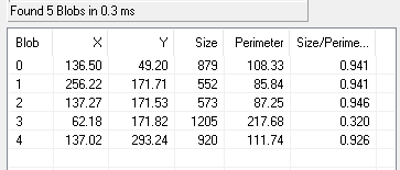
Example: Blob detection on a bracket based on grey value thresholds using C# Blob Detection Example CSBlobExample.exe:
BLOB_BLACK and BLOB_WHITE define the threshold range to be recognized as an object (blob).
Threshold Range uses minimum and maximum gray value for binarizing.
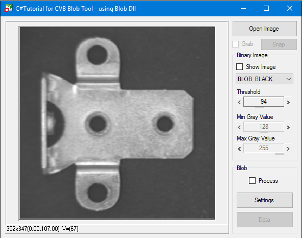
Depending on the threshold values the blobs are detected:
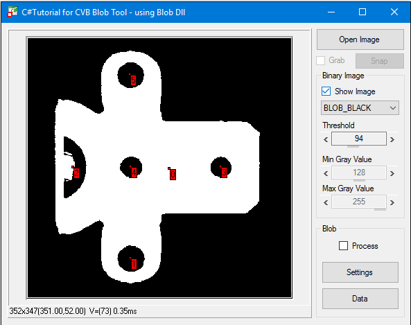
Detailed parameters can be determined reading Blob data of e.g. Blob 3:
Example: Setting Threshold Range min gray value = 0 and max gray value to same threshold as with BLOB_BLACK you get the same result as BLOB_BLACK.
Setting Threshold Range min gray value to same threshold as with BLOB_WHITE and max gray value = 255 in given example you get the same result as BLOB_WHITE.
Initially, the Blob tool analyzes the specified area of interest (AOI) and generates the run length code using the binary threshold.
The tool runs through the AOI row for row and column for column and, whenever an object begins in a row, enters the line number, startpoint and endpoint (called a streak from now on) in a table.
Example 1: Analysis of white objects:

MinAreaHoleSize=3 is specified for the size of the holes, then we have:Example 2: Analysis of white objects again

In the next step, the streak data is combined into contiguous objects and transferred to the tables taking the filters into account (see Filter functions).
The object parameters are then calculated for these objects only.
Area:
The area of an object corresponds to the number of pixels that make up the object. See e.g. the functions BlobGetSize and BlobGetConvex.
Perimeter:
The sum of all X transitions + Y transitions + SQRT(2)*XY transitions.
|
|---|
Object size (area) = 1 pixel, perimeter = 4 |
|
|---|
Object size (area) = 2 pixels, perimeter = 6 |
|
|---|
Object size (area) = 3 pixels, perimeter = 6+1*SQRT(2) |
Bounding Box:
The bounding box of an object is a rectangle with the width and heigth of the object.
How to extract it: see function BlobGetBoundingBox.
|
|---|
| Object of arbitrary shape with bounding box |
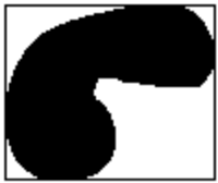
Moments:
Moments are object-dependent parameters which describe the orientation of non-symmetrical objects.
Note that circular objects do not have any orientation (see BlobGetMoments).
The ratio of the minimum moment of inertia to the maximum moment of inertia indicates how pronounced the orientation is.
|
|---|
Object with pronounced orientation showing the axis of the minimum moment of inertia. The BlobGetMinMomentPoints function returns the startpoint and endpoint of the straight line. |
|
|---|
| Object without pronounced orientation |
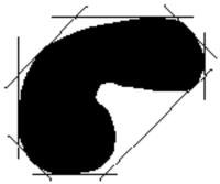
Convex perimeter:
The convex perimeter approximates better to the actual perimeter than the bounding box but returns much less data than, for example, the chaining code or streak data.
For the convex parameter, projections are applied to the object from different sides.
The simplest case is the boundary box with two projections at an angle of 90° to each other.
|
|---|
| Object of arbitrary shape with bounding box |
The perimeter is calculated more precisely when the number of projections is doubled, and operations are based on steps of 45° instead of 90°.
The BlobGetConvexPoints function returns the coordinates of the points that lie on the convex perimeter.
The number of projections can be set with the BlobSetNumFeret function. BlobGetNumFeret returns the number of points on the convex perimeter.
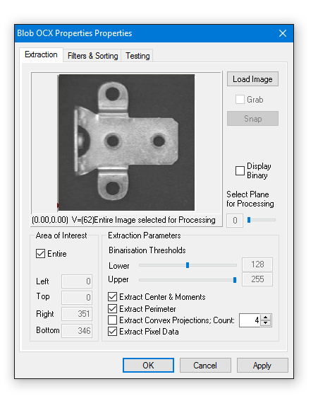
The ActiveX Control CVBlob.ocx is described here.
Example: Blob detection on a bracket based on grey value threshold value setting using VC Blob Demo from cvbTutorial\Blob\VC:

Blob parameter values can be read in property pages.

In addition to the standard properties dialog you can select and change most properties in the Property Pages of the Blob Control.
This is a convenient way to setup the tool.