|
|
Common Vision Blox 14.0
|
|
|
Common Vision Blox 14.0
|

Common Vision Blox Tool
 C-Style |  C++ | ") .Net API (C#, VB, F#) |  Python |
| Match3D.dll | Cvb::Match3D | Stemmer.Cvb.Match3D | cvb.match_3d |
In many production environments it is important that each product is checked for completeness and flaws. It is a common approach to compare a golden template image (model) with an image of the test object (part). Therefore the object's image is simply subtracted from the model image. However, in practice the two images have to be perfectly aligned. This requires a transformation prior to the comparison step in order to move the part to the same position and orientation of the model. For objects in 2D a translation in x and y and one rotation have to be found. Whereas, aligning objects in 3D (point clouds) is more complex. Here, a translation in x, y and z and a rotation about the x-, y-, and z-axis have to be estimated. This results in 6 Degrees of Freedom (DoF) for the 3D case, as opposed to 3 DoF in the 2D case.
The core part of the Match3D tool is following function which aligns two point clouds in all 6 DOF: CVM3DMatchDownsampledPointClouds
In addition, a function is provided calculating the RMS of two point clouds: CVM3DRmsDistanceOfPointClouds
Note, that general functions handling 3D data (e.g. computing the euler angels from a rotation matrix and vice versa, transforming point clouds, loading a point cloud from a file, etc...) are implemented in the Core3D.dll.
For the quality inspection of a part, it has to be compared to a model. Before the inspection part and model have to be perfectly aligned. The process of the alignment of two point clouds is described in the section Alignment. In order to compare the point clouds they have to be reprojected along the z-axis and their differences have to be computed (see section Comparision of two point clouds).
Before two surfaces can be compared to each other, they have to be properly aligned in 3D. This can be done using the function CVM3DMatchDownsampledPointClouds, the core part of Match3D. CVM3DMatchDownsampledPointClouds is based on the iterative closest point algorithm (ICP) that follows Arun K., Huang T., Blostein S. (1987) "Least-squares fitting of two 3-D point sets" in IEEE Trans Pattern Anal Machine Intell 9:698–700. It is based on a least-squares fit which iteratively estimates a translation in x, y, z and a rotation matrix with the angles about the x-, y- and z-axis (roll, pitch and yaw).
Although the ICP is a stable and fast algorithm a coarse pre-alignement of the point clouds is required. For a successfully matching both input surfaces must meet the following conditions:
The function CVM3DMatchDownsampledPointClouds needs as input two organized or unorganized point clouds saved as CVCOMPOSITE handle (see also the Core.dll). In addition several input parameters can be set:
With these parameters the accuracy of the alignment and the computation speed can be optimized. The output of CVM3DMatchDownsampledPointClouds is a translation vector (x, y, z) and a rotation matrix, stored in a CVC3DTransformation object.
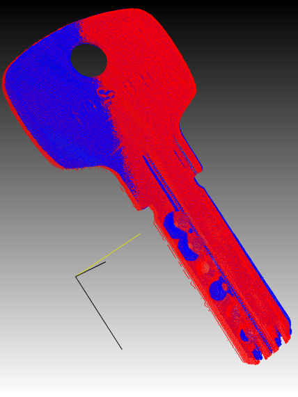
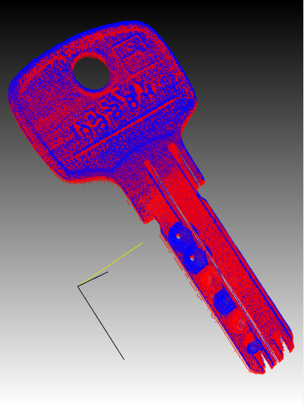
With the Core3D function CVC3DRollPitchYawFromRotationMatrix the euler angles (roll, pitch, yaw) can be computed from the rotation matrix (see Core3D.dll). In addition, a rough accuracy assessment of the matching results can also be done calculating the RMS with the function CVM3DRmsDistanceOfPointClouds. However, for the final quality inspection the differences between the model and the transformed point cloud have to be computed. This can be done by re-projecting the point clouds along the z-axis and computing the differences (see section Comparision of two point clouds). The following figures show two point clouds before (top) and after (bottom) the alignment. The blue points represent the model (golden template or reference object) and the red points represent the part to be inspected and aligned.
Since CVB 14.0 an improved alignement with function CVM3DMatchPointCloudsAdvanced is provided. The function matches two point clouds by an extended iterative closest point algorithm (ICP), which also takes shape correspondence into consideration. The point cloud may be pre-aligned using the center of gravity (if this option is selected by the user). Note, that the two objects may not be tilted by more than about 30° or even 60° depending on the their shape.
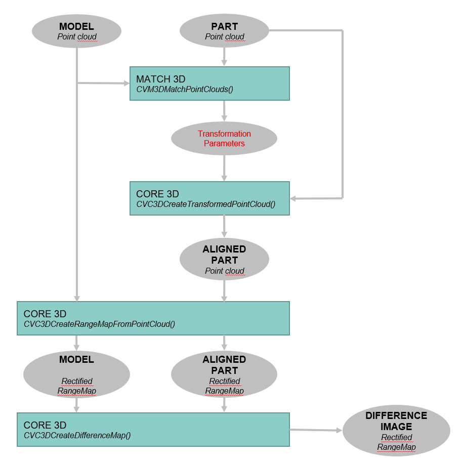
For the final quality inspection, the aligned point cloud has to be compared to the model. Therefore several functions of the Core3D.dll can be used: In a first step both point clouds (model and target) must be reprojected along the z-axis by the function CVC3DCreateRangeMapFromPointCloud. The output will be a 2D image, we call it a rectified range map. Afterwards, the point differences between both surfaces can be computed using the function CVC3DCreateDifferenceMap, which simply subtracts the previously generated rectified images from each other.
The whole process of matching and creating a disparity map is shown in the flow chart below.
An example application can be found in %cvb%Tutorial\Match3D. A brief VC++ example is provided below.
Two point clouds are loaded and matched. Afterwards they are converted into rectified range maps and a difference map is created from these images.