The IImageVPA interface provides rapid access to image pixels in cases where the image is represented in memory in some VPA-compatible format.
In addition to the usual QueryInterface, Addref and Release, IImageVPA contains the following functions:
ImageDimension
Returns the dimension of the image object, i.e. the number of image planes. The image planes are accessed by an index and all indexed functions below are defined for
0 <= Index < (IMDimension - 1).
ImageWidth/Height
Logical width and height of the image. This is how wide and high the image should appear to the processing software.
All planes of the image have this logical width and height which needn't match their actual width and height in memory - SourceWidth and SourceHeight below.
Virtual image dimensions can be used to control aspect ratios of non-square pixel frame grabbers or for pyramids.
ImageDatatype(Index)
Returns the data type of a pixel value in the image plane given by Index.
The format for the encoding of data types should include the bit count (8-bit is probably the most frequent) and flags to specify signed or unsigned numbers or possibly floating point numbers where there is any ambiguity (e.g. for 32 bits).
Our proposal is to use a Dword to identify the data type where the lowest byte defines the bit count and bits 8 and 9 stand for signed/unsigned and float/integer, respectively.
Higher bits are free to implement user-specific flags (i.e. ColorBGR, as may be desired for one of the examples presented).
ImageVPA (Index)
Returns the address of the VPA table for the Index-th image plane and the base address of the image plane.
The VPA table is an array of simple 8-byte structures containing the two Dword fields XEntry and YEntry.
Details on the size of this array and its precise definition follow in the complete definition of the interfaces.
GetImageCoords/SetImageCoords
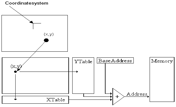
Sets and returns the current coordinate system. The coordinate system is defined by the origin and a 2x2 matrix which represents scaling and rotation.
These functions are implemented in a semantically correct way if the scalar value of the pixel (X, Y) in the Index-th image plane can be addressed using the following equation:
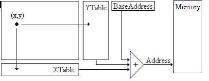
Address := BaseAddress (Index) + VPAT (Index)[X].Xentry + VPAT (Index)[Y].YEntry.
The following figure shows the mechanism of pixel addressing with VPA without using the coordinate system:

The following figure shows the mechanism of pixel addressing with VPA using the coordinate system:

Suppose that for some processing routine the index of the image plane in question has been fixed, and that the two pixel coordinates (X, Y) reside in the general registers (ecx, edx) and the value of VPAT in ebx.
Then the assembler statements
mov eax, BaseAddress ; load base address
add eax,[ebx+8*ecx] ; add XTable(X) - scaled addressing
add eax,[ebx+8*edx+4] ; add YTable(Y) - scaled addressing
compute the pixel address.
This involves a minimum of 5 processor cycles (no cache miss on BaseAddress and the tables).
Three cycles are to be added if the VPAT and the coordinates have to be moved to memory first.