General workflow to create calibrated point cloud
There are a variety of 3D sensors available and many different concepts and output formats. Some output pre-calibrated range maps, where a metric point cloud can be generated by just applying static factors. Others output uncalibrated range maps. Sometimes these uncalibrated range maps come with a set of intrinsic calibration parameters, sometimes it is necessary for users to calibrate a current sensor setup by themselves.
The following flow charts demonstrate the principle of CVB handling different input range maps and how to generate desired point clouds:
Case 1 - Convert calibrated range map into point cloud of sensor coordinate system
In this case the sensor outputs pre-calibrated range maps with corresponding static factors for X, Y and Z. The static calibration parameters can be set to a calibrator handle. These factors will be applied to a calibrator handle. The acquired range map and the calibrator will together generate the point cloud. The resulting coordinate system of the point cloud is according to the sensor definitions.
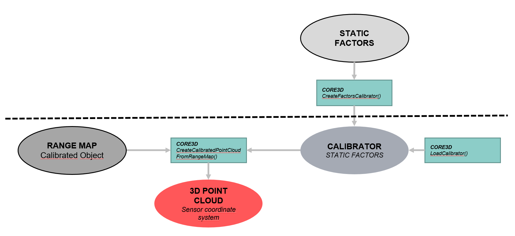
Calibrated range maps may not only have static factors in x,y,z but also static offsets in x,y and z. If this is the case an additional transformation on the 3D point cloud has to be done using function TransformPointCloud() where the rotation matrix is set to identical (not shown in flow chart).
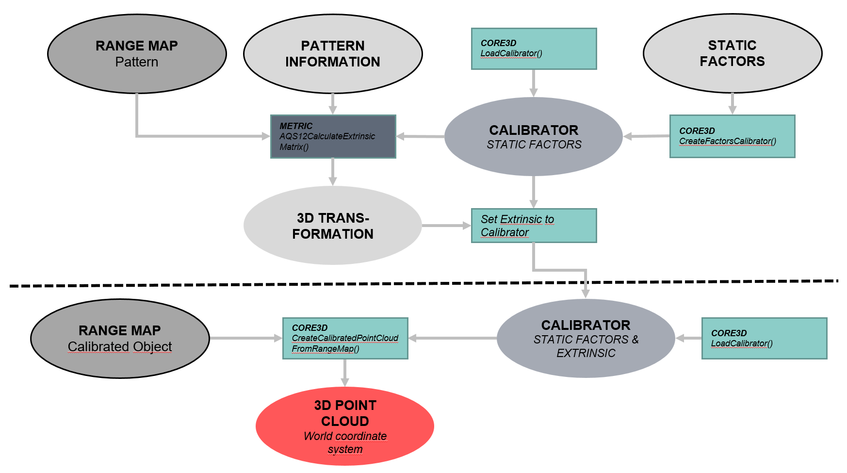
Case 2 - Convert calibrated range map into point cloud of world coordinate system
In this case the sensor outputs pre-calibrated range maps with corresponding static factors. The static calibration parameters can be set to a calibrator handle. In order to transform a resulting point cloud into the desired world coordinate system, the calibrator handle will be updated with extrinsic calibration parameters. These parameters have to be calculated using the Metric function CVMAQS12CalculateCorrectionOfLaserPlaneInclinationFromPiece() or CVMAQS12CalculateRigidBodyTransformationFromPiece() with the AQS12 pattern or on any other way. The acquired range map and the calibrator will together generate the point cloud. The resulting coordinate system of the point cloud is the desired world coordinate system. For detailed information about the calibration with CVB and the AQS12 target see section "Foundation Package -> Foundation API -> Foundation Tools -> Metric".
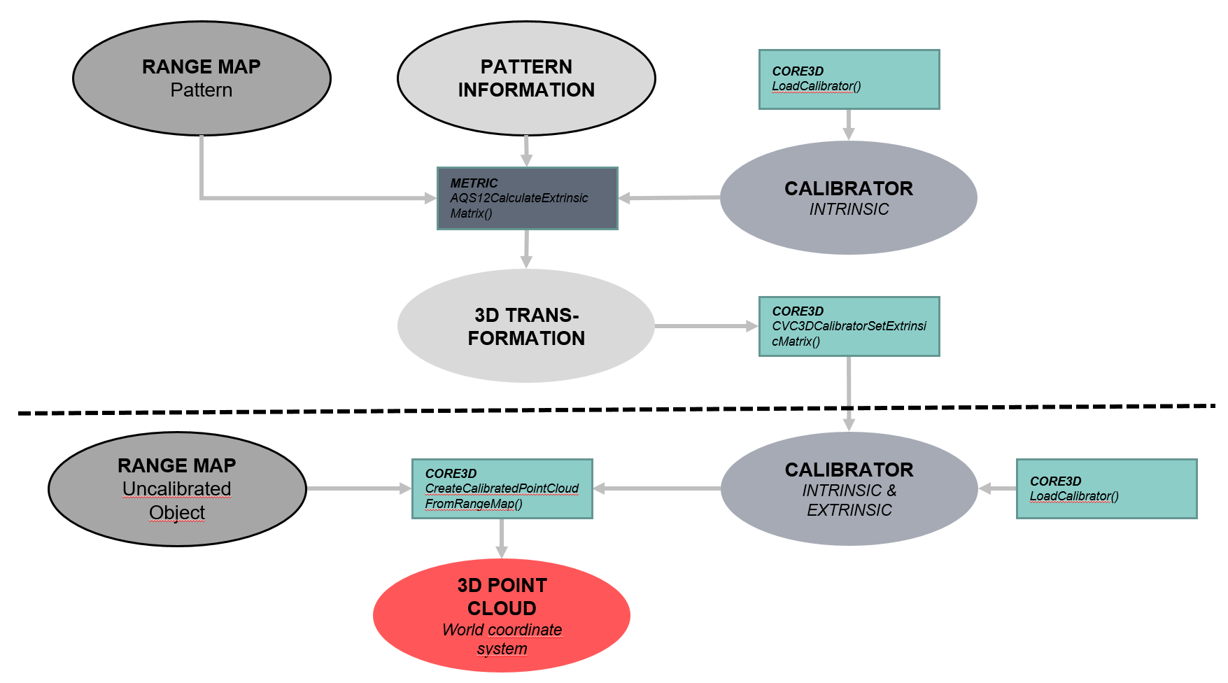
Case 3 - Convert uncalibrated range map with given intrinsic calibration parameters into point cloud of world coordinate system
In this case the sensor outputs uncalibrated range maps, but with corresponding intrinsic calibration parameters The intrinsic calibration parameters can be set to a calibrator handle by loading it from a calibration file. In order to transform a resulting point cloud into the desired world coordinate system, the calibrator handle will be updated with extrinsic calibration parameters. These parameters have to be calculated using the Metric function CVMAQS12CalculateCorrectionOfLaserPlaneInclinationFromPiece() or CVMAQS12CalculateRigidBodyTransformationFromPiece() with the AQS12 pattern or on any other way. CVMAQS12CalculateCorrectionOfLaserPlaneInclinationFromPiece() estimates an affine matrix which is strictly speaking an intrinsic parameter, as the affine matrix corrects errors resulting from an inclined laser plane (laser plane is not exactly vertical to the movement direction) . CVMAQS12CalculateRigidBodyTransformationFromPiece() calculates a rigid-body transformation, which only includes rotation and translation. The acquired range map and the calibrator will together generate the point cloud. The resulting coordinate system of the point cloud is the desired world coordinate system.
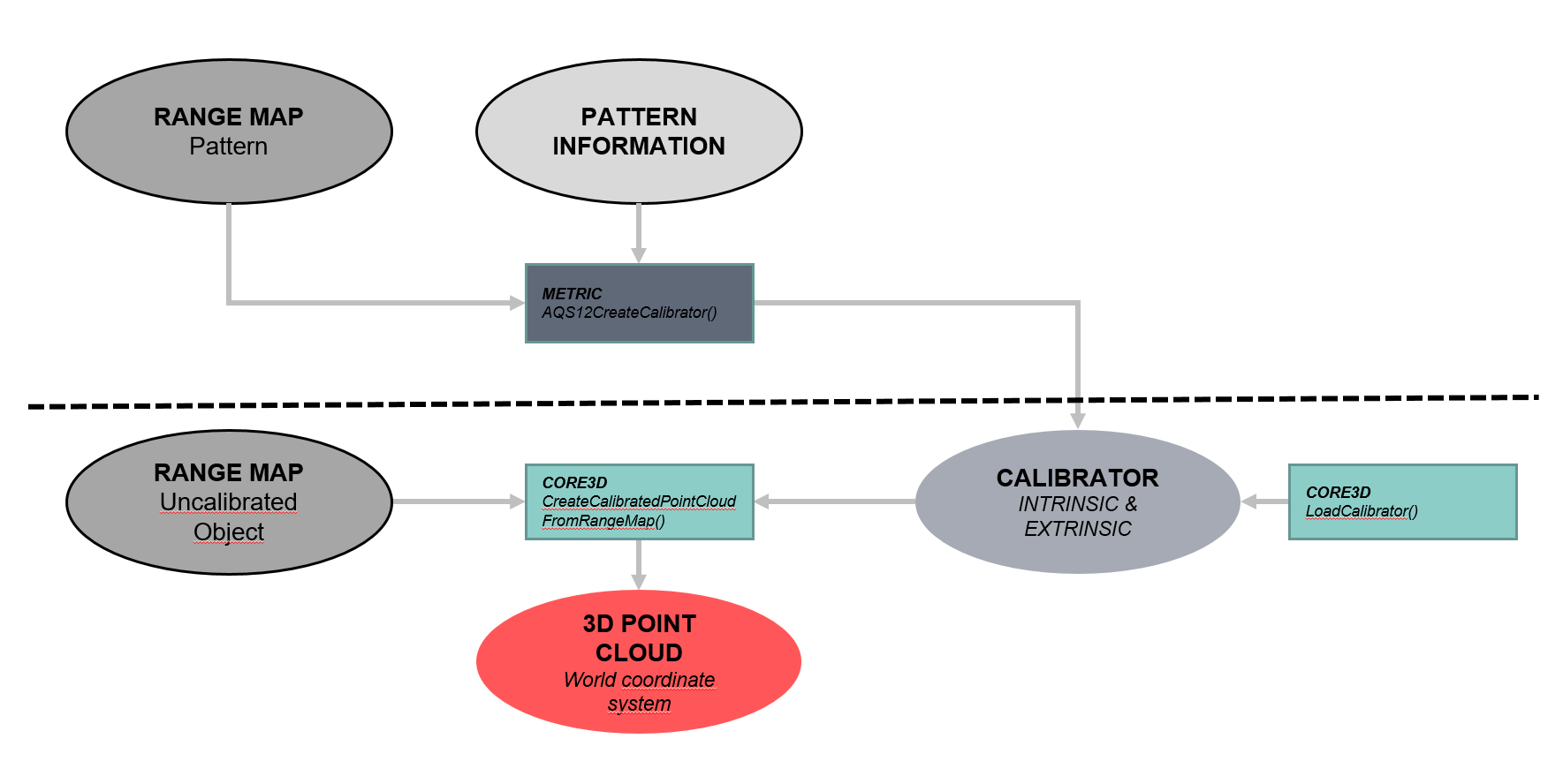
Case 4 - Convert uncalibrated range map into point cloud of world coordinate system
In this case the sensor outputs uncalibrated range maps, with no additional information (e.g. a modular triangulation system). A calibrator handle can be generated using the Metric function CVMAQS12CreateIntrinsicCalibratorFromPiece() or any other way. Both, the intrinsic and extrinsic parameters will be stored in the calibrator handle. The acquired range map and the calibrator will together generate the point cloud. The resulting coordinate system of the point cloud is the desired world coordinate system. For detailed information about the calibration with CVB and the AQS12 target see section "Foundation Package -> Foundation API -> Foundation Tools -> Metric".
As can be seen in these flow charts the generation of a point cloud always requires a range map and a calibrator object. However, a calibrator can consist of different calibration types.
Create calibrated point cloud with modified sensor settings
One import point to be aware of, is that the calibration parameters stored in the calibrator always refer to the whole sensor (with no mirroring of the pixel coordinates). If the sensor settings of a camera indicate that a sensor region of interest (ROI) is given or pixel coordinates are mirrored, the range map values will be transformed to the sensor coordinates before applying the calibration parameters. In practice especially users of AT cameras have to be careful. In the AT or ZigZag calibration file the default sensor settings are stored. They refer to
•the sensor settings set acquiring the target for the ZigZag calibration (json file).
• or the sensor settings set when the calibration file (xml) was loaded from the AT compact sensor.
If the user acquires a range map with settings that differ from the default ones stored in the calibrator, he may not use the standard function CVC3DCreateCalibratedPointCloudFromRangeMap! Instead he should use function CVC3DCreateCalibratedPointCloudFromRangeMapWithSettings, where he is called upon setting the correct sensor settings. With function CVC3DCalibratorGetSettings the default settings stored in the calibrator can be loaded. CVB release 14.0 supports the following settings, which are described in detail here:
•CVC3DSensorSettings::RangeScale: The range map values will be scaled by this factor. It can be calculated from ![]() , where NumSubpixel is the number of subpixels.
, where NumSubpixel is the number of subpixels.
•CVC3DSensorSettings::PixelPosition: The pixel position in Y may be absolute or relative. If it is relative, the sensor coordinates relative to OffsetTop are used for the range map creation. If this parameter is set to absolute, OffsetTop is set to zero in the calibraton files.
•CVC3DSensorSettings::PixelsMirrored: If this parameter is set, the x and/or y sensor coordinates of the profile are mirrored.
•CVC3DSensorSettings::OffsetLeft: Left offset of sensor ROI.
•CVC3DSensorSettings::OffsetTop: Top offset of sensor ROI.
•CVC3DSensorSettings::Width: Width of sensor ROI.
•CVC3DSensorSettings::Height: Height of sensor ROI.
•CVC3DSensorSettings::ResolutionReductionHorizontal: Horizontal resolution reduction factor due to sensor binning.
•CVC3DSensorSettings::ResolutionReductionVertical: Vertical resolution reduction factor due to sensor binning.
•EncoderStep: Encoder step (factor for values in movement direction).
In the following table the different settings (1st column) are listed and their notation in the camera properties (2nd column), the AT calibration file (3rd column) and the ZigZag calibration file (4th column). Until now CVB only supports sensor settings of AT cameras.
CVB parameter |
Camera |
AT file (xml) |
ZigZag file (json) |
|---|---|---|---|
RangeScale |
has to be calculated from Cust::NumSubPixel |
intrinsic.rangeScale |
3rd value of intrinsic.factors |
PixelPosition |
Cust::AbsOffsetPos |
OffsetTop = 0 |
intrinsic.sensorsettings.mode. absolutepositiony |
PixelsMirrored |
std::ReverseX |
Width is negative |
intrinsic.sensorsettings.mode.reverse.x |
std::ReverseY |
Height is negative |
intrinsic.sensorsettings.mode.reverse.y |
|
OffsetLeft |
std::OffsetX |
intrinsic.sensorRoi |
intrinsic.sensorsettings.sensorroi |
OffsetTop |
Cust::AoiOffsetY |
||
Width |
std::Width |
||
Height |
Cust::AoiHeight |
||
ReductionResolutionHorizontal |
not supported yet |
intrinsic.rrH |
not supported yet |
ReductionResolutionVertical |
not supported yet |
intrinsic.rrV |
not supported yet |
EncoderStep |
not available |
extrinsic.Sy |
2nd value of intrinsic.factors |